F3 DIO 8/8 01 4 Start-up
HI 800 179 E Rev. 2.00 Page 39 of 52
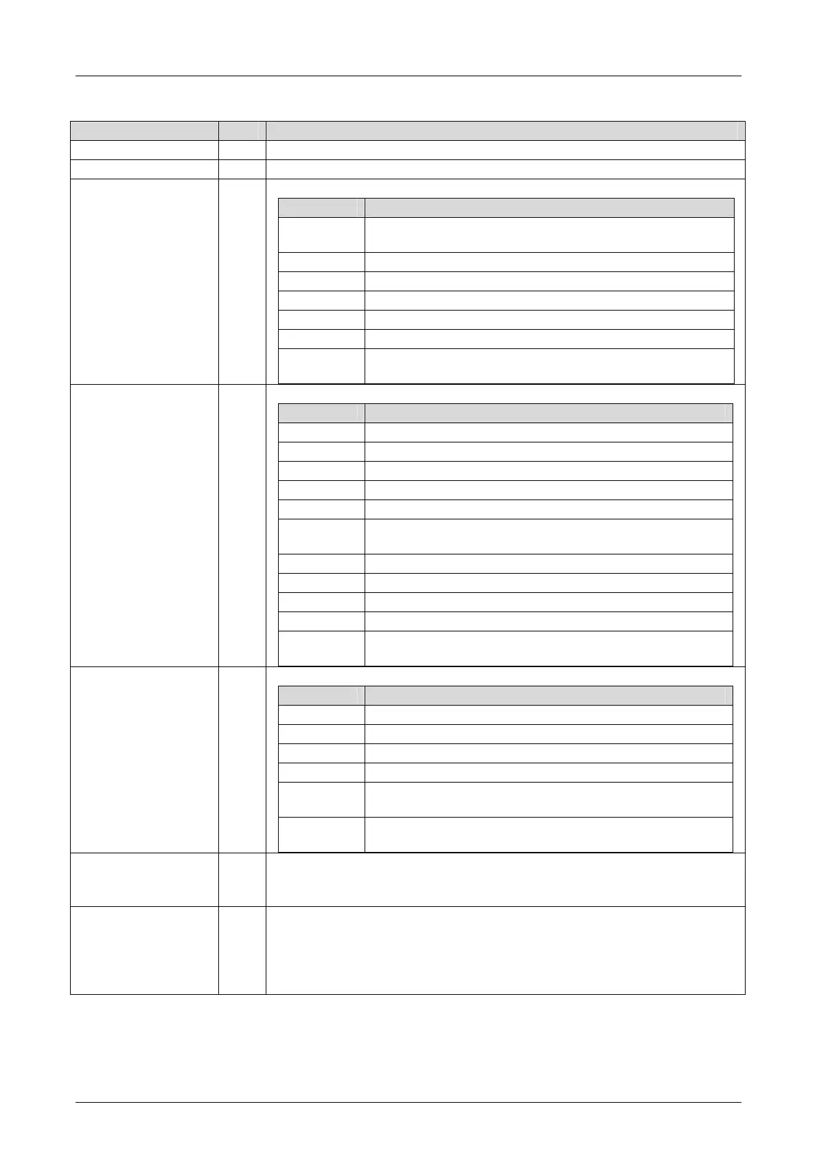
4.4.4 Digital Outputs of F3 DIO 8/8 01, DO+ (DO1), DO- (DO2)
System Signal R/W Description
Mod.SRS [UDINT] R Slot number (System Rack Slot)
Mod. Type [UINT] R
Type of module, target value: 0x005B [91
dec
]
Mod. Error Code
[WORD]
R Module error code
Coding Description
0x0000
I/O processing, if required with errors, see other error
codes
0x0001 No I/O processing (CPU not in RUN)
0x0002 No I/O processing during the booting test
0x0004 Manufacturer interface operating
0x0010 No I/O processing: invalid configuration
0x0020 No I/O processing: fault rate exceeded
0x0040/
0x0080
No I/O processing: configured module not plugged in
DOy.Error Code
[WORD]
y = 1 or 2
R Error codes for all digital outputs
Coding Description
0x0001 Fault within the digital outputs
0x0002 Test of safety shutdown returns a fault
0x0004 Test of auxiliary voltage returns a fault
0x0008 FTT test of test pattern faulty
0x0010 Output switch test pattern faulty
0x0020
Output switch test pattern (shutdown test of the outputs)
faulty
0x0040 Active shutdown via WD faulty
0x0200 All outputs are switched off, total current exceeded
0x0400 FTT test: 1st temperature threshold exceeded
0x0800 FTT test: 2nd temperature threshold exceeded
0x1000
FTT test: Monitoring of auxiliary voltage 1:
Undervoltage
DOyxx.Error Code
[BYTE]
y = 1 or 2
R Error codes for the digital output channels
Coding Description
0x01 Fault in the digital output module
0x02 Channel shutdown due to overload
0x04 Error while reading back the digital outputs
0x08 Error while reading back the status of the digital outputs
0x40
External short-circuit or short-circuit of the EMC protection
returns an error
0x80
Channel is switched off due to fault on the corresponding
channel
DOy[xx].Value
[BOOL]
y = 1 or 2
W Output value for DO channels:
1 = output energized
0 = output de-energized
DO2[xx].2-Pole
[BOOL]
W Configuration for a 2-Pole channel
1 = DO2[01] and DO1[04] are used as a 2-pole channel
or
DO2[02] and DO1[08] are used as a 2-pole channel
0 = DO2[xx] is not used as a 2-pole channel.

 Loading...


