4 Start-up F3 DIO 8/8 01
Page 38 of 52 HI 800 179 E Rev. 2.00
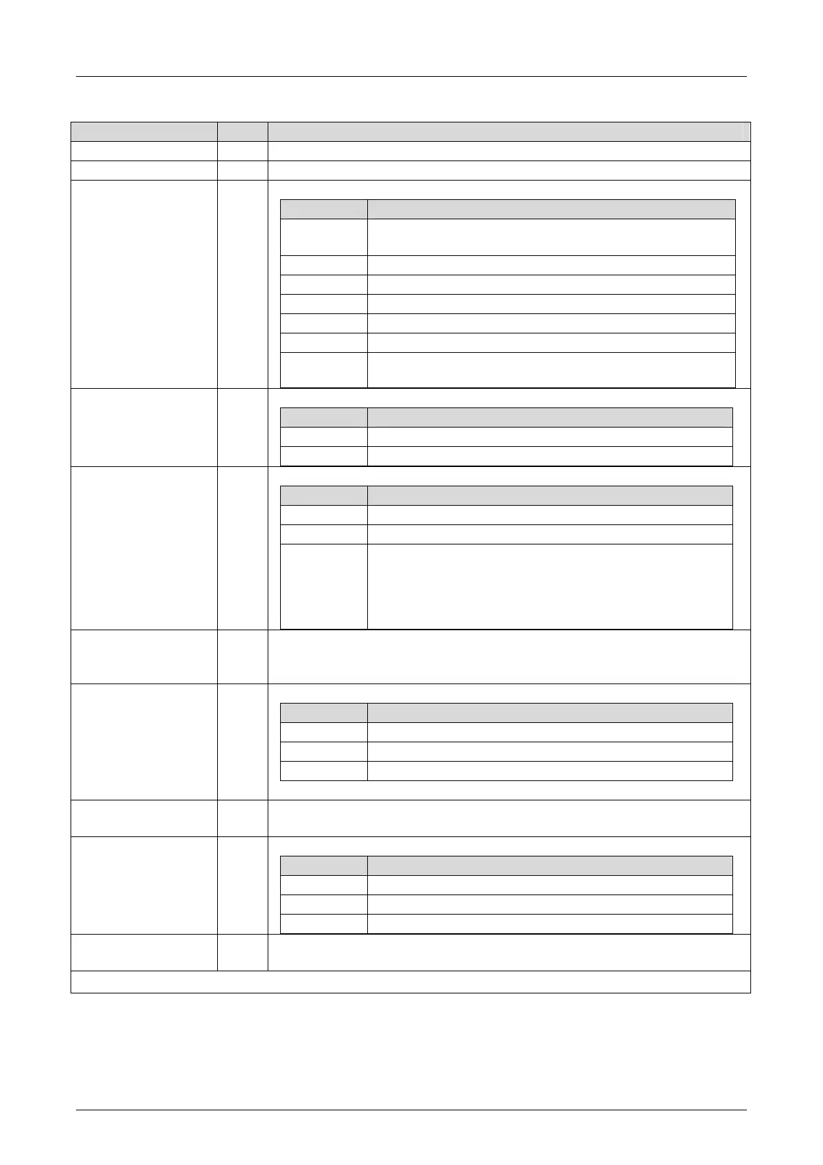
4.4.3 Digital Inputs of F3 DIO 8/8 01
System Signal R/W Description
Mod.SRS [UDINT] R Slot number (System Rack Slot)
Mod. Type [UINT] R Type of module, target value: 0x00A5 [165
dec
]
Mod. Error Code
[WORD]
R Module error code
Coding Description
0x0000 I/O processing, if required with errors
see other error codes
0x0001 No I/O processing (CPU not in RUN)
0x0002 No I/O processing during the booting test
0x0004 Manufacturer interface operating
0x0010 No I/O processing: invalid configuration
0x0020 No I/O processing: fault rate exceeded
0x0040/
0x0080
No I/O processing: configured module not plugged in
DI.Error Code
[WORD]
R Error codes for all digital inputs
Coding Description
0x0001 Fault within the digital inputs
0x0002 FTT test of test pattern faulty
DI[xx].Error Code
[BYTE]
R Error codes for the digital input channels
Coding Description
0x01 Fault in the analog input module
0x10 Short-circuit of the channel
0x80
Intermittence between pulsed output TO and digital input
DI, e.g.,
Open-circuit
Open switch
L+ undervoltage
DI[xx].Value [BOOL] R Input values for the digital input channels
0 = input de-energized
1 = input energized
DI Number of
Pulsed Channels
[USINT]
W Number of pulsed outputs (supply outputs)
Coding Description
0 No pulsed output planned for SC/OC
1)
detection
1 Pulsed output 1 planned for SC/OC
1)
detection
2 Pulsed output 1 and 2 planned for SC/OC
1)
detection
Pulsed outputs must not be used as safety-related outputs!
DI Pulse Slot
[UDINT]
W Pulse module slot (SC/OC
1)
detection), set the value to 3
DI[xx].Pulsed Output
[USINT]
W Source channel for pulsed supply
Coding Description
0 Input channel
1 Pulse of the 1st TO channel
2 Pulse of the 2nd TO channel
DI Pulse Delay
[10E-6 s] [UINT]
W Waiting time for line control (detection of short-circuits or cross-circuits)
1)
SC/OC (SC = short-circuit, OC = open-circuit)
Table 29: ELOP II Factory - Digital Input System Signals

 Loading...


