31
―――――――――――――――――――――――――――
Chapter 2 Measurement Procedure
――――――――――――――――――――――――
NOTE
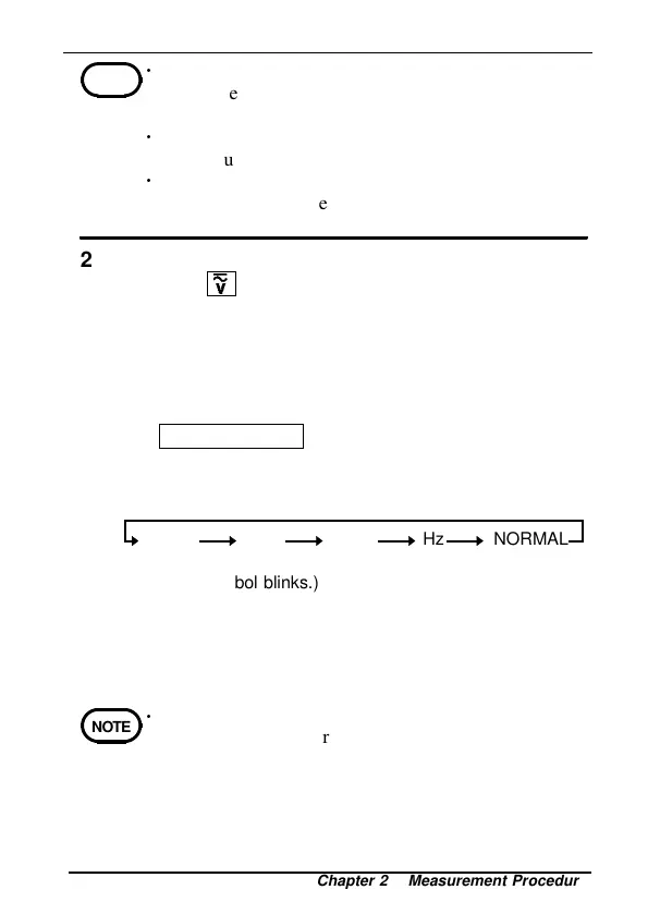
SLOW PEAKFAST
(The unit
symbol blinks.)
Hz NORMAL
NOTE
2.4.2 Fre
uenc
Measurement in Volta
e Mode
・
The frequencies, whose waveforms are special such
as inverters, would not be measurable, when the
carrier frequencies are lower than several kHz.
・
Full-wave rectification indicates twice the actual
value, due to an AC coupling in the internal circuit.
・
It would take time to stabilize the counter,
depending on the frequency range or the input
frequency.
1. Press
and select AC or AC+DC, depending on
the circuit to be measured.
2. If the voltage range of the measured circuit is
known, set the voltage range to the manual range.
3. Slide the slide cover up using the slide knob. Next,
insert the red test lead to V and the black test lead
to COM of the voltage measurement terminal.
4.
SLOW/PEAK/Hz
switches the annunciators as
follows. Select Hz by pressing the key. (The unit
symbol V blinks, and a voltage value is displayed
on the bar graph.)
5. Switch between the auto range and the manual range
as necessary.
6. Attach or remove the rigid insulating sleeve as
required by the measurement category.
7. Carefully contact the test leads to a circuit.
・
Be sure to use the test leads with the sleeves
attached when performing measurements in the CAT
III measurement category. In a CAT II
environment, if the tips of the test leads do not
reach the measurement object, remove the rigid
insulating sleeve before measuring.