Hope Electronics Technology Manual Edition V1.0 74
Chapter 9 Appendix
Appx. 1 block diagram
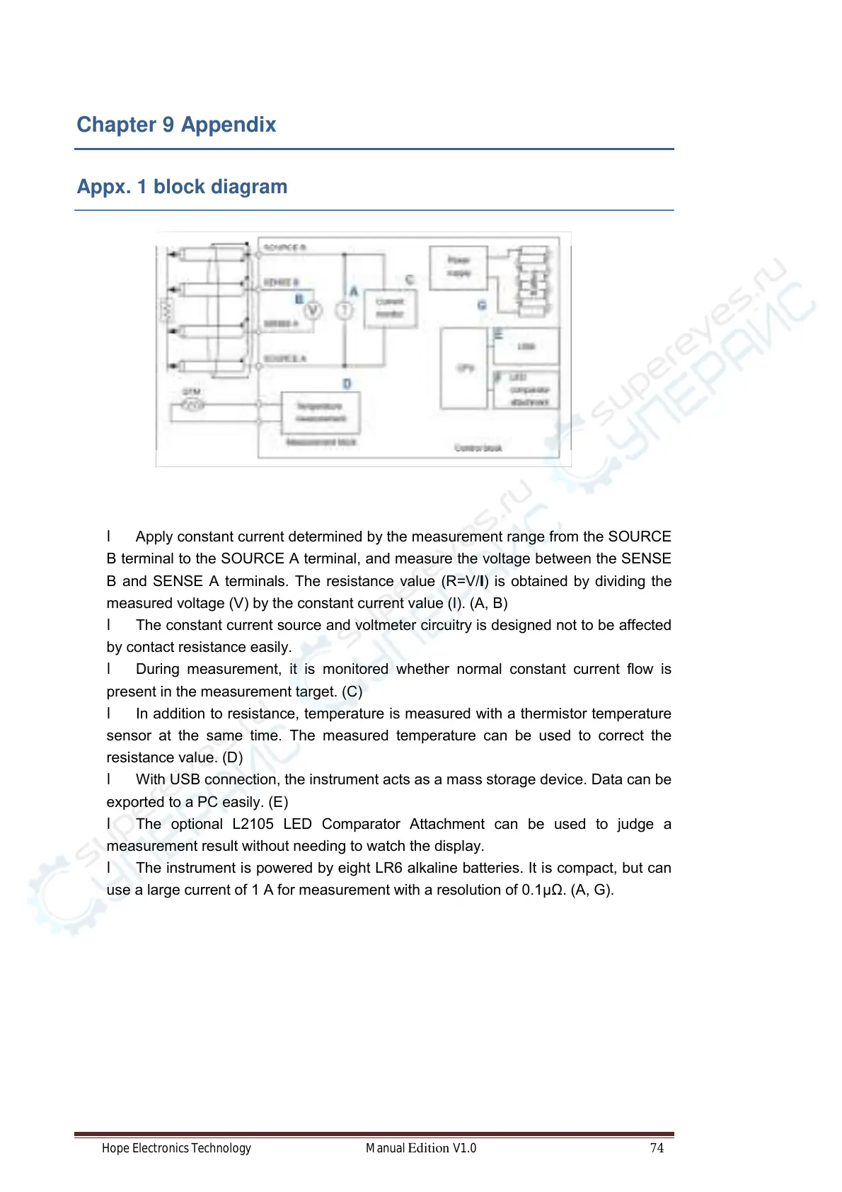
l Apply constant current determined by the measurement range from the SOURCE
B terminal to the SOURCE A terminal, and measure the voltage between the SENSE
B and SENSE A terminals. The resistance value (R= V/I) is obtained by dividing the
measured voltage (V) by the constant current value (I). (A, B)
l The constant current source and voltmeter circuitry is designed not to be affected
by contact resistance easily.
l During measurement, it is monitored whether normal constant current flow is
present in the measurement target. (C)
l In addition to resistance, temperature is measured with a thermistor temperature
sensor at the same time. The measured temperature can be used to correct the
resistance value. (D)
l With USB connection, the instrument acts as a mass storage device. Data can be
exported to a PC easily. (E)
l The optional L2105 LED Comparator Attachment can be used to judge a
measurement result without needing to watch the display.
l The instrument is powered by eight LR6 alkaline batteries. It is compact, but can
use a large current of 1 A for measurement with a resolution of 0.1μΩ. (A, G).