M3X8 button bolt
EXø5ボール台付
EXø5 ball with stand
シーソー
Seesaw
Collar 2.6X4X12S
M2.6X15CS
FWø2.6Xø5X0.5
カラー 2.6X4X12S
14
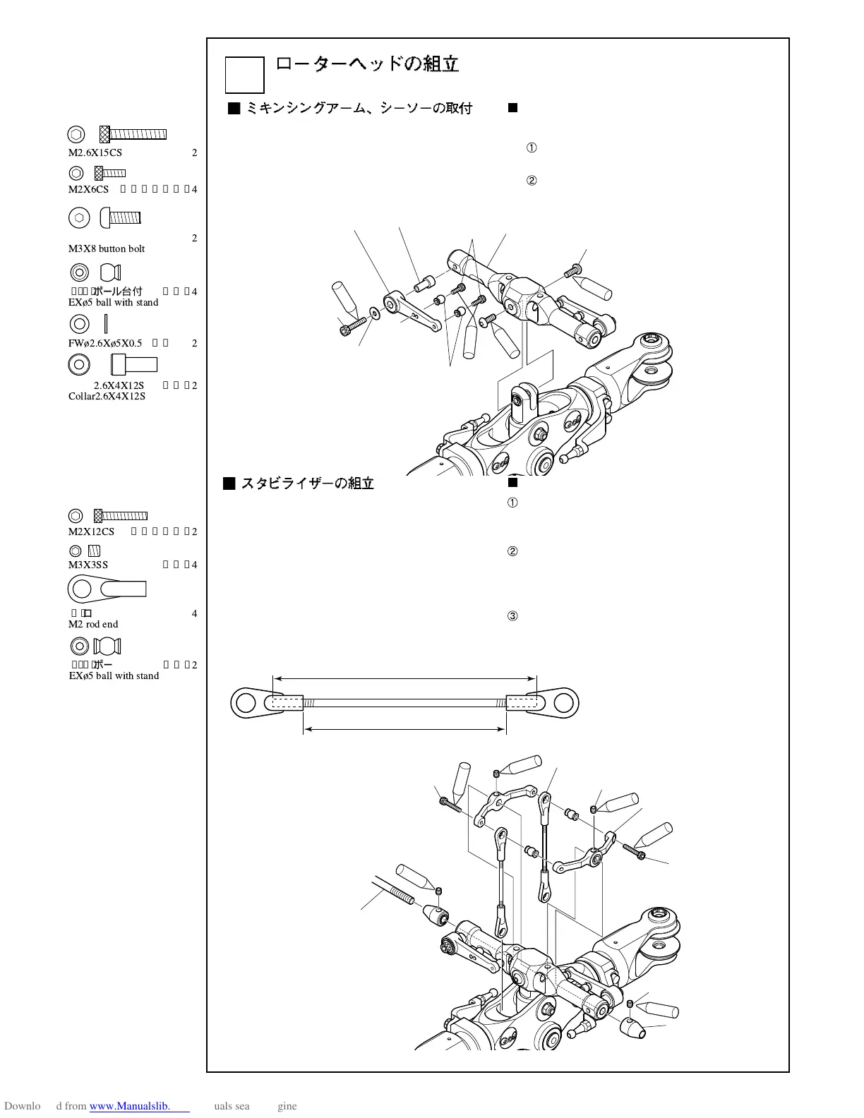
Rotor head assembly
① ミキシングアームにφ 5 ボール台付を M2 × 6CS
で取付けます。
② シーソーをセンターハブにM3 ×8 ボタンボルト
で取付けます。
Attachment of the mixing arm and the
seesaw
Attach the ø5 ball with stand to the mixing arm
with M2X6CS.
Attach the seesaw to the center hub with M3X8 button
bolts.
① シーソーの中間部でスタビコントロールアーム
を組立て、スタビライザーバーをシーソーとス
タビコントロールアームに通します。
② シーソーの両側からスタビライザーバーにスタ
ビストッパーを通し、スタビライザーバーが
シーソーを中心に左右同じ長さになり、移動し
ないよう M3 × 3SS で固定します。
③ スタビライザーバーの位置が決まったら、スタ
ビコントロールアームのボールがセンターハブ
の中心線上になるようM3×3SSでスタビコント
ロールアームを固定します。
Assembling the stabilizer
Assemble the stabilizer control arm at the seesaw
intermediate part, and pass the stabilizer bar through the
seesaw and stabilizer control arm.
Insert the stabilizer bar through the stabilizer bar stoppers
at both sides of the seesaw so that the left and right sides
have the same lengths from the center, and fix the bar
with the M3 x 3SS so as not to move.
After the stabilizer bar is positioned, fix the stabilizer
control arm with the M3 x 3SS so that the ball of the
stabilizer control arm is on the center line of the center
hub.
M3X8ボタンボルト ………
2
M3X8 button bolt
EXφ5ボール台付 ………
4
EX¿5 ball with stand
M2ロッドエンド …………
4
M2 rod end
カラー
2.6X4X12S
………
2
Collar2.6X4X12S
M2X6CS
…………………
4
M2X12CS
………………
2
FW¿2.6X¿5X0.5
…………
2
M2.6X15CS
………………
2
M3X3SS
…………………
4
EXφ5ボール台付 ………
2
EX¿5 ball with stand