Installation GRS1020/1120/1030/1130
Release
03
01/2017
21
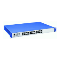
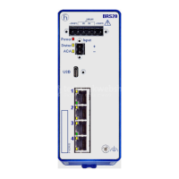
1.4 Device views
1.4.1 Front view
1 Grounding screw
2 Connection for the signal contact
3 16 × RJ45 socket for 10/100 Mbit/s twisted pair connections
4 Cover panel
5 Supply voltage connection 1
alternatively,
depending on
device variant
Supply voltage with the
characteristic value C
2-pin terminal block
Supply voltage with the
characteristic value M
3-pin terminal block
6 Supply voltage connection 2
alternatively,
depending on
device variant
Supply voltage with the
characteristic value C
2-pin terminal block
Supply voltage with the
characteristic value M
3-pin terminal block
Table 4: Front view using example of device variant GRS1120
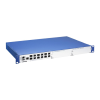
1 USB interface
2V.24 interface
3 Grounding screw
4 LED display elements
5 4 × Combo port for 10/100/1000 Mbit/s connections
6 16 × RJ45 socket for 10/100 Mbit/s twisted pair connections
7 Cover panel
Table 5: Front view using example of device variant GRS1030
2
1
5
6
3
4
 Loading...