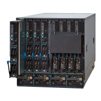
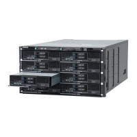
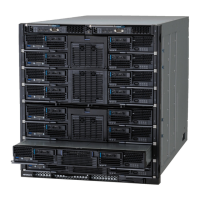
1 Gb/sec LAN Pass-through Module
Figure 1-37 1 Gb/sec LAN Pass-through Module
Table 1-20 1 Gb/sec LAN Pass-through Module Indicators and Connectors
Location Name State Description
1 LAN ports 0 to 15 Green-On Link established.
Green-Blink Link communication
Amber-On No link.
2 Identify LED (LOCID) Blue-On The LAN pass-through module is
identified.
3 Power LED (PWR) Green-On Powered-on, normal operation.
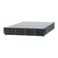
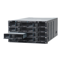
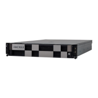
10 Gb/sec LAN Pass-through Module
Figure 1-38 10 Gb/sec LAN Pass-through Module
Table 1-21 10 Gb/sec LAN Pass-through Module Indicators and
Connectors
Location Name State Description
1 LAN ports 0 to 15 - By default these ports do not have
transceivers installed. The type of
transceiver varies according to
usage.
2 Power LED (PWR) Green-On Powered on normally.
3 Status 1 LED (ST1) Green-On Powered on.
Green-Blink In initial diagnostics or in initial
setting.
Red-On An error is detected.
1-32
System Overview
Hitachi Compute Blade 500 Series System Overview Guide
 Loading...


