L300P Inverter Specifications
Getting Started
1–10
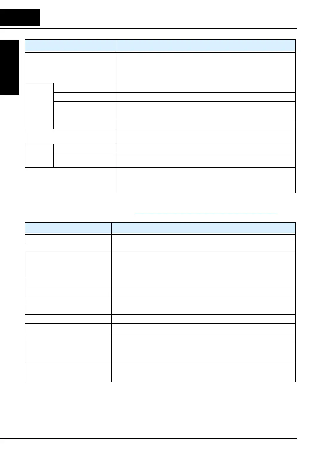
Signal Ratings Detailed ratings are in “Specifications of Control and Logic Connections” on page 4–8.
Protective functions Over-current, overload, braking resistor overload, over-voltage, EEPROM error, under-
voltage error, CT (current transformer) error, CPU error, external trip, USP error,
ground fault, input over-voltage, instantaneous power failure, inverter thermal trip,
phase failure detection, IGBT error, thermistor error, expansion card 1 error, expansion
card 2 error, under-voltage waiting error
Environ-
ment
Temperature *10 Operating (ambient): -10 to 40°C / Storage: -20 to 65°C
Humidity 20 to 90% humidity (non-condensing)
Vibration *7
Models L300P–110xxx to 300xxx: 5.9 m/s
2
(0.6G), 10 to 55 Hz
Models L300P–370xx to 1320xxx: 2.94 m/s
2
(0.3G), 10 to 55 Hz
Location *8 Altitude 1,000 m or less, indoors (no corrosive gasses or dust)
Coating color Models L300P–110xxx to 750xxx: Blue (D.I C14 version No. 436)
Models L300P–900xx to 1320xxx: Gray (MUNSELL 8.5YR6.2/0.2)
Accessories Digital input PCB SJ-DG (4-digit BCD / 16-bit binary)
Others EMI filters, input/output reactors, DC reactors, radio noise filters, braking resistors,
braking units, LCR filter, communication cables, factory I/O network interface cards
Operator input devices *9 OPE–SRE (4-digit LED with potentiometer) / OPE–S (4-digit LED w/o potentiometer),
Optional: OPE-SR (4-digit LED with potentiometer, Japanese/English overlay),
SRW–0EX Multilingual operator with copy function (English, French, German, Italian,
Spanish, and Portuguese)
Item General Specifications
Signal / Contact Ratings
Built-in power for inputs 24VDC supply, 100 mA maximum
Intelligent (programmable) logic inputs 27VDC maximum, 4.7kΩ input impedance
Intelligent (programmable) logic outputs Relay type, normally open contacts (1 Form A)
250 VAC / 30 VDC, 5A (resistive load) maximum
250 VAC / 30 VDC, 1A (inductive load) maximum
Minimum 5 VDC, 1mA
Thermistor input Minimum thermistor power 100mW
PWM output 0 to 10VDC, 1.2 mA max., 50% duty cycle
Voltage analog output 0 to 10VDC, 2 mA max.
Current analog output 4-20 mA, nominal load impedance 250Ω
Analog input, current 4 to 19.6 mA range, 20 mA nominal
Analog input, voltage 0 to 9.6 VDC range, 10VDC nominal, 12VDC max., input impedance 10 kΩ
+10V analog reference 10VDC nominal, 10 mA maximum
Alarm relay, normally closed contacts Maximum loads: 250VAC, 2A; 30VDC, 8A resistive load
250VAC, 0.2A; 30VDC, 0.6A inductive load
Minimum loads: 100 VAC, 10mA; 5VDC, 100mA
Alarm relay, normally open contacts 250VAC, 1A; 30VDC 1A max. resistive load /
250VAC, 0.2A; 30VDC, 0.2A max. inductive load
Min. loads: 100 VAC, 10mA; 5VDC, 100mA

 Loading...


