“D” Group: Monitoring Functions
Configuring Drive
Parameters
3–6
“D” Group: Monitoring Functions
Parameter
Monitoring
Functions
You can access important system parameter values with the “D” Group monitoring functions,
whether the inverter is in Run Mode or Stop Mode. After selecting the function code number
for the parameter you want to monitor, press the Function key once to show the value on the
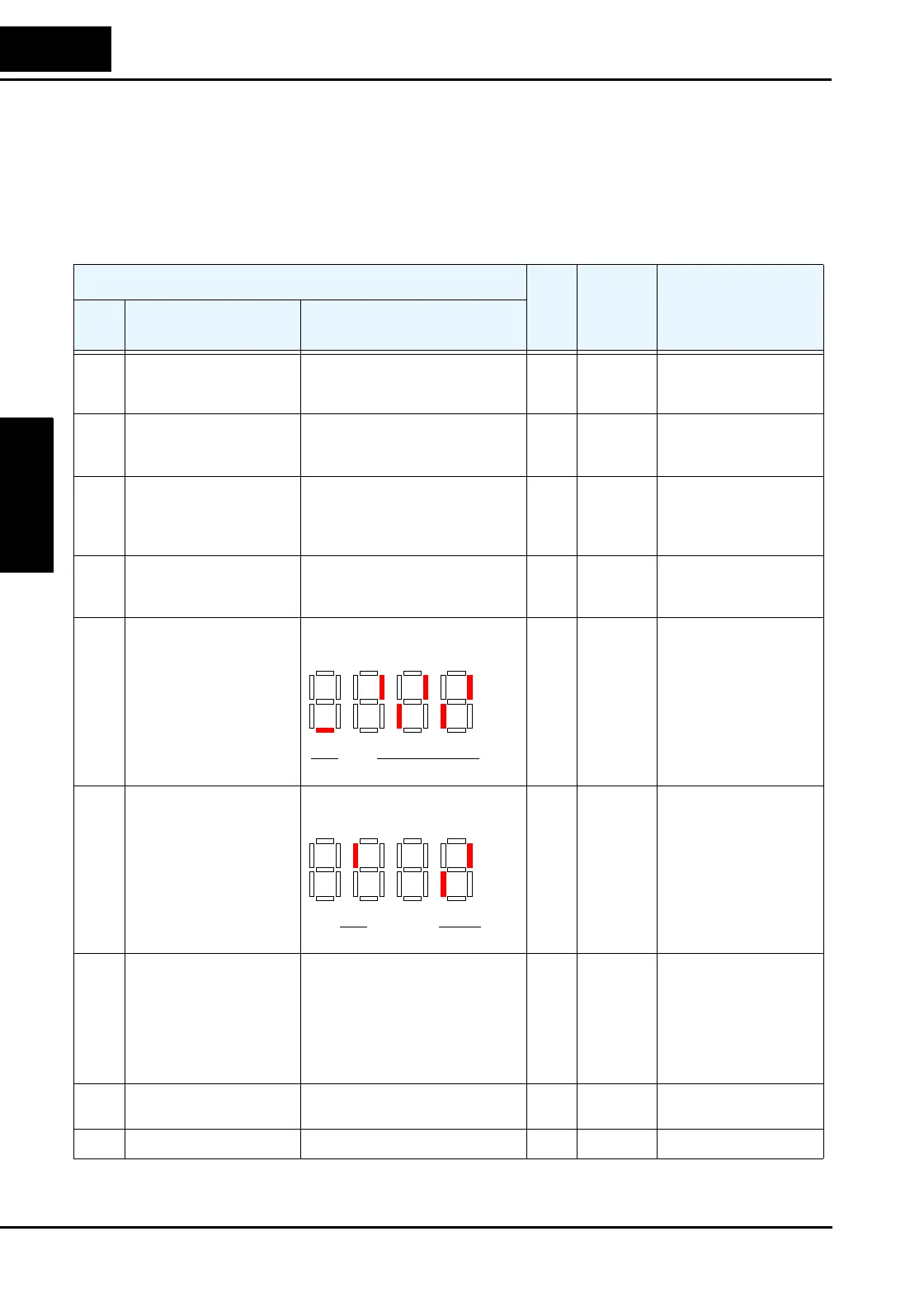
display. In Functions D005 and D006 the intelligent terminals use individual segments of the
display to show ON/OFF status.
“D” Function
Run
Mode
Edit
Range
and Units
SRW Display
Func.
Code
Name Description
D001 Output frequency monitor Real-time display of output
frequency to motor, from 0.0 to
400.0 Hz
—
0.0 to
400.0 Hz
FM 0000.00Hz
D002 Output current monitor Filtered display of output current
to motor (100 mS internal filter
time constant)
—
A
Iout 0000.0A
D003 Rotation direction
monitor
Three different indications:
“F”. Forward
“o”. Stop
“r” Reverse
——Dir STOP
D004 Process variable (PV),
PID feedback monitor
Displays the scaled PID process
variable (feedback) value (A75 is
scale factor)
——PID-FB 0000.00%
D005 Intelligent input terminal
status
Displays the state of the intelligent
input terminals:
——IN-TM LLLLLLLLL
D006 Intelligent output terminal
status
Displays the state of the intelligent
output terminals:
——OUT-TM LLLLLL
D007 Scaled output frequency
monitor
Displays the output frequency
scaled by the constant in B86.
Decimal point indicates range:
XX.XX 0.00 to 99.99
XXX.X 100.0 to 999.9
XXXX. 1000 to 9999
XXXX 10000 to 99990
—
User-
defined
F-CNV 000000.00
D013 Output voltage monitor Voltage of output to motor,
range is 0.0 to 600.0V
—
VA C
Vout 000.0V
D014 Power monitor 0.0 to 999.9 —
kW
Power 000.0kW
ON
OFF
12345
Terminal numbers
FW
ON
OFF
11
Terminal numbers
12AL

 Loading...


