xiv
Fuse and Circuit
Breaker Sizes
The inverter’s input power wiring must include UL Listed, dual-element, 600V fuses, or UL
Listed, inverse-time, 600V circuit breakers.
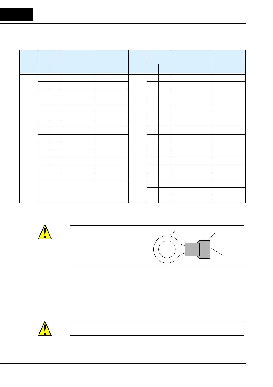
Wire Connectors
WARNING: Field wiring connections must
be made by a UL Listed and CSA Certified
ring lug terminal connector sized for the
wire gauge being used. The connector must
be fixed using the crimping tool specified by
the connector manufacturer.
Motor Overload
Protection
Hitachi L300P inverters provide solid state motor overload protection, which depends on the
proper setting of the following parameters:
• B012 “electronic overload protection”
• B212 “electronic overload protection, 2nd motor”
Set the rated current [Amperes] of the motor(s) with the above parameters. The setting range is
0.2 * rated current to 1.2 * rated current.
WARNING: When two or more motors are connected to the inverter, they cannot be protected
by the electronic overload protection. Install an external thermal relay on each motor.
Input
Vol ta ge
Motor
Output
200V
Inverter Models,
L300P
Ampere Rating
for Fuse or
Breaker
Input
Voltage
Motor
Output
400V
Inverter Models,
L300P
Ampere Rating
for Fuse or
Breaker
HP kW HP kW
200V
2 1.5 -015LFU2 10
400V
2 1.5 -015HFU2, HFE2 10
3 2.2 -022LFU2 15 3 2.2 -022HFU2, HFE2 10
5 3.7 -037LFU2 20 5 4.0 -040HFU2, HFE2 15
7.5 5.5 -055LFU2 30 7.5 5.5 -055HFU2, HFE2 15
10 7.5 -075LFU2 40 10 7.5 -075HFU2, HFE2 20
15 11 -110LFU2 60 15 11 -110HFU2, HFE2 30
20 15 -150LFU2 70 20 15 -150HFU2, HFE2 35
25 18.5 -185LFU2 90 25 18.5 -185HFU2, HFE2 50
30 22 -220LFU2 100 30 22 -220HFU2, HFE2 50
40 30 -300LFU2 150 40 30 -300HFU2, HFE2 70
50 37 -370LFU2 175 50 37 -370HFU2, HFE2 80
60 45 -450LFU2 200 60 45 -450HFU2, HFE2 100
75 55 -550LFU2 250 75 55 -550HFU2, HFE2 125
100 75 -750LFU2 300 100 75 -750HFU2, HFE2 150
125 90 -900HFU2, HFE2 200
150 110 -1100HFU2, HFE2 225
175 132 -1320HFU2, HFE2 300
Terminal (ring lug)
Cable support
Cable

 Loading...


