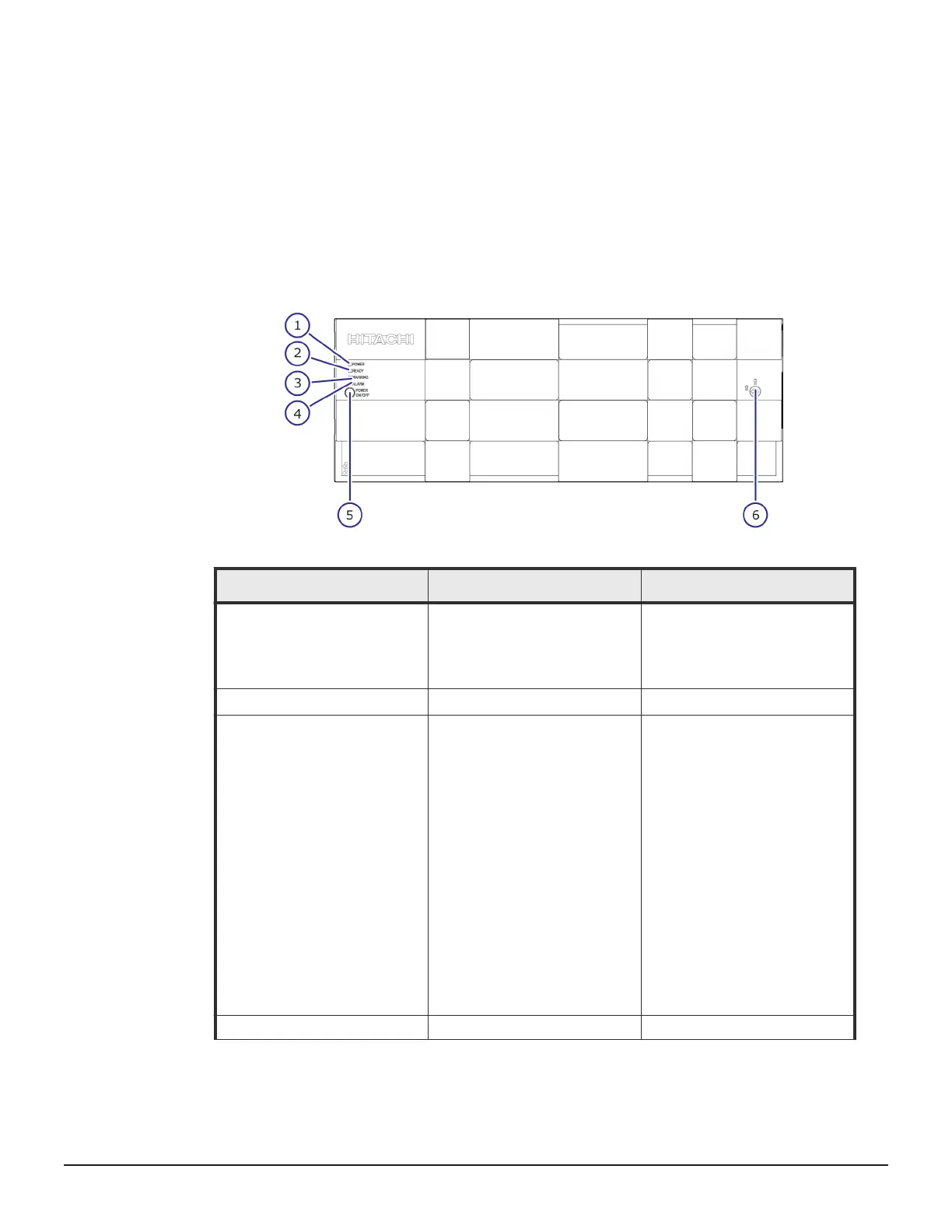
CBLM controller
The CBLM controller includes specific functional LEDs located on the front and
rear of controller and power supplies to provide its operating status.
CBLM with front panel bezel
The following table describes the definitions of the CBLM controller front
panel bezel LEDs.
Number
Item Description
1
POWER LED Green: Storage system is
powered on.
Amber: Storage system is
receiving power.
2
READY LED Green: Normal operation.
3 WARNING LED
Off: Normal operation.
Amber: Component requires
maintenance.
Blink: Failure requires
maintenance.
Note: When System Option
Mode 1097 is set to ON, the
WARNING LED does not blink,
even if the following failure
service information messages
(SIM) are issued: 452xxx,
462xxx, 3077xx, 4100xx, and
410100.
LED might turn off during user
maintenance.
4
ALARM LED Off: Normal operation.
28 Virtual Storage Platform G400, G600 controller
Hitachi Virtual Storage Platform G400, G600 Hardware Reference Guide
 Loading...