OM-947 Page 11
SECTION 3 − DEFINITIONS
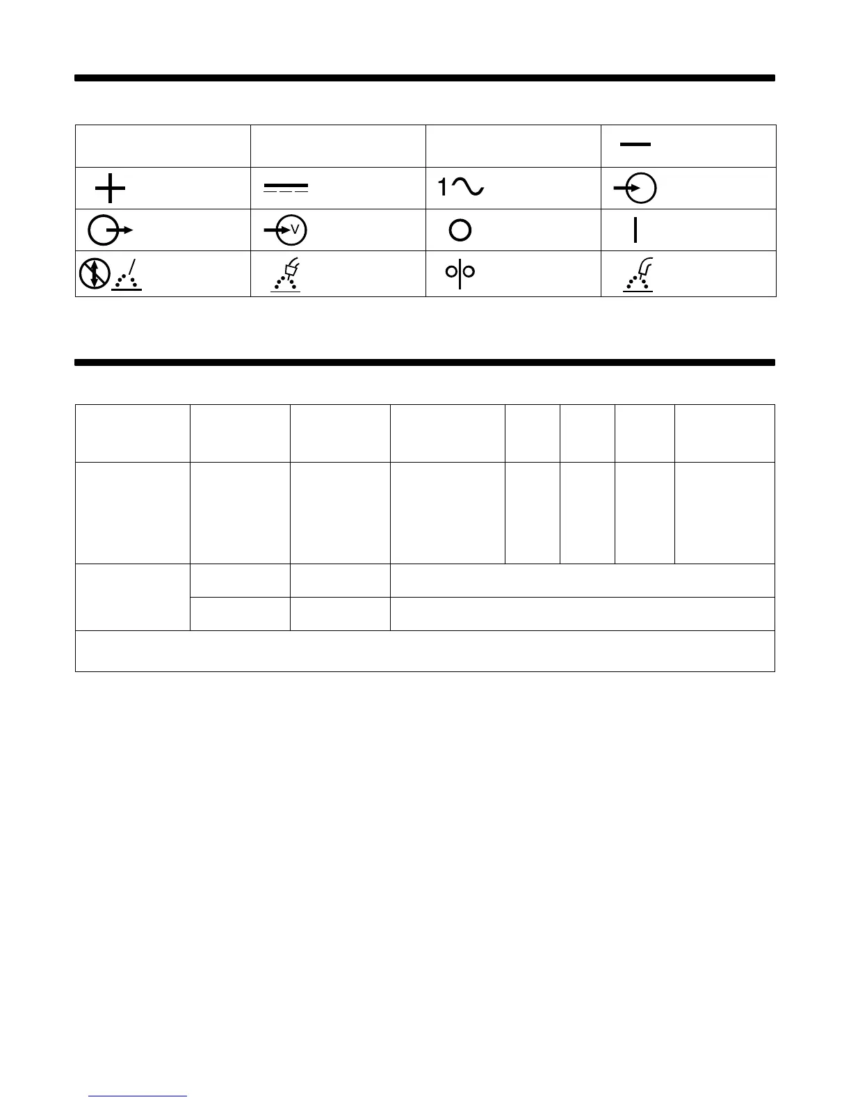
3-1. Symbols And Definitions
A
Amperage
V
Voltage
Hz
Hertz Negative
Positive
Direct Current
(DC)
Single Phase Input
Output Voltage Input Off On
Do Not Switch
While Welding
Gas Metal Arc
Welding (GMAW)
Wire Feed
Flux Cored Arc
Welding (FCAW)
SECTION 4 − SPECIFICATIONS
4-1. Specifications
Rated Welding
Output
Amperage
Range
Maximum Open-
Circuit Voltage
DC
Amperes Input at
Rated Load Output
115 V, 60 Hz, Single-
Phase
KVA KW
Weight
W/ Gun
Overall
Dimensions
85 A @ 17.5 Volts
DC, 20% Duty Cycle
60 A @ 20 Volts DC,
20% Duty Cycle*
30 − 125
26
20
15*
2.90
2.20*
2.50
1.77*
50 lb
(22.7 kg)
Length: 16-7/8 in.
(429 mm)
Width: 9-7/8 in.
(251 mm)
Height: 12-1/8 in.
(308 mm)
Wire Type
And Dia
Flux Cored Solid/
Stainless**
Wire Feed Speed Range
.030 − .035 in.
(0.8 − 0.9 mm)
.024 − .030 in.
(0.6 − 0.8 mm)
0 − 500 IPM (0 − 13 m/min) At No Load
0 − 415 IPM (0 − 11 m/min) Feeding Wire
* CSA Rating
** When shielding gas is required, MIG conversion kit 195 158 must be installed.