OM-947 Page 20
SECTION 6 − OPERATION
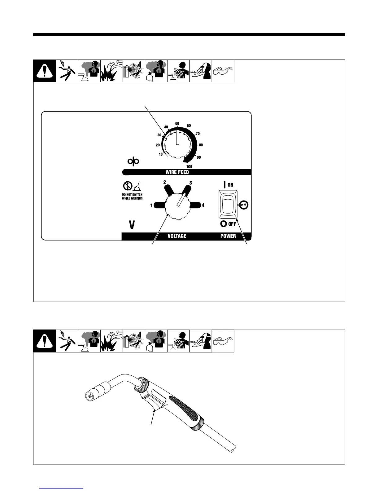
6-1. Controls
1 Voltage Switch
Use control to select the weld
voltage range. As the thickness of
material increases, a higher voltage
range must be selected (see weld
setting label in welding power
source or Section 6-3 as
applicable). Do not switch under
load.
. Switch must “click” into detent
position for weld output.
2 Wire Feed Control
Use control to select a wire feed
speed. As Voltage switch setting in-
creases, wire speed range also in-
creases (see weld setting label in
welding power source or Section
6-3 as applicable).
3 Power Switch
Ref. 229 999-A
1
2
3
6-2. Operating The Gun
Ref. 804 240-A
1 Trigger Switch
When pressed, energized wire
feeds and shielding gas flows (if
unit is equipped with optional gas
solenoid).
1