EasyManuals Logo

Hobart Handler 125 User Manual

Hobart Handler 125
52 pages
To Next Page IconTo Next Page
To Previous Page IconTo Previous Page
Page #18 background imageLoading...
Page #18 background image
OM-947 Page 14
5-2. Process/Polarity Table
Process Polarity
Cable Connections
Cable To Gun Cable To Work Clamp
FCAW Self-shielding wire
no shielding gas
DCEN Straight Polarity Connect to negative ()
output terminal
Connect to positive (+) output
terminal
GMAW* Solid wire with
shielding gas
DCEP Reverse polarity Connect to positive (+) out-
put terminal
Connect to negative () output
terminal
* Unit must have MIG conversion kit 195 158 installed.
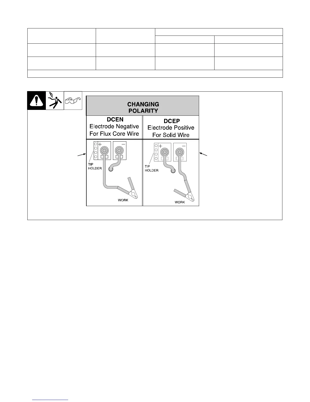
5-3. Changing Polarity
1 Lead Connections For Direct
Current Electrode Negative
(DCEN)
2 Lead Connections For Direct
Current Electrode Positive
(DCEP)
Always read and follow wire
manufacturer’s recommended po-
larity, and see Section 5-2.
Close door.
Ref. 210 428
1
2

Table of Contents

Other manuals for Hobart Handler 125

Questions and Answers:

Question and Answer IconNeed help?

Do you have a question about the Hobart Handler 125 and is the answer not in the manual?

Hobart Handler 125 Specifications

General IconGeneral
Input Voltage115V
Amperage Output25-125A
Duty Cycle20% @ 90A
Weldable MaterialsSteel, Stainless Steel, Aluminum
Weight57 lbs
ProcessesMIG (GMAW)
Maximum Material Thickness3/16 inch
Wire Size0.023-0.035 inch

Related product manuals