OM-316 Page 17
Return To Table Of Contents
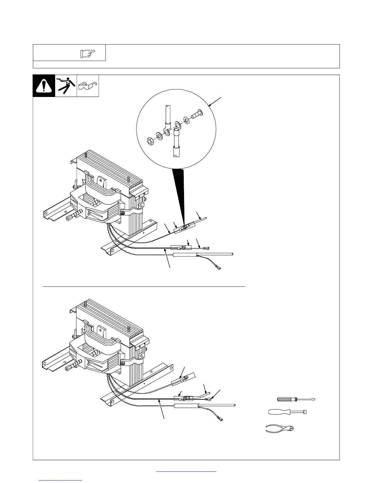
3-9. Internal Connections For Operating 230/400 Volts, 300/200 Amperes AC/DC Or 300
Amperes AC Models From 230 Volts
Follow applicable electrical codes and have a competent electrician make internal
connections. Note the input amperes as stated in Section 3-7.
NOTE
Ref. ST-802 247-D
1
2
3
4
5
6
7
2
3
5
6
Connected For 400 Volts
Connected For 230 Volts
5/16, 3/8 in
(cut tie wraps)
Y Turn Off unit and disconnect
input power.
1 Primary Coil Lead 4
2 Lead 4 Insulation Sleeving
3 Power Switch Lead 4
4 Lead Connection Hardware
Slide Sleeving down, and discon-
nect one lead 4 from the other. Re-
move sleeving.
5 Fan Motor (FM) Lead 2
6 Lead 2 Insulation Sleeving
Disconnect fan motor lead 2 at fan
motor, and remove sleeving.
Take lead 2 sleeving and secure it
over the end of primary coil lead 4.
Replace lead 2 sleeving with lead 4
sleeving.
7 Primary Coil Lead 2
Slide sleeving out of the way, and
connect power switch Lead 4 to pri-
mary coil lead 2, and secure with
existing hardware. Secure sleeving
over connection.
Connect fan motor lead 2 back onto
fan motor.
Reinstall wrapper.
7
Tools Needed:
 Loading...