Home
Hobart
Welding System
STICKMATE LX
Hobart STICKMATE LX User Manual
4
of 1
of 1 rating
48 pages
Give review
Manual
Specs
To Next Page
To Next Page
To Previous Page
To Previous Page
Loading...
OM-316 Page 30
Return T
o T
able Of Contents
7-2.
Electrode
And Amperage Selection Chart
Ref. ST-087 985-A
3/32
1/8
5/32
3/16
7/32
1/4
1/16
5/64
3/32
1/8
5/32
3/16
7/32
1/4
3/32
1/8
5/32
3/16
7/32
1/4
3/32
1/8
5/32
3/16
7/32
1/4
3/32
1/8
5/32
3/16
7/32
1/4
3/32
1/8
5/32
3/16
3/32
1/8
5/32
6010
&
601
1
6013
7014
7018
7024
Ni-Cl
308L
50
100
150
200
250
300
350
400
450
ELECTRODE
DC*
AC
POSITION
PENETRA
TION
USAGE
MIN. PREP
, ROUGH
HIGH SP
A
TTER
GENERAL
SMOOTH, EASY
,
F
AST
LOW HYDROGEN,
STRONG
SMOOTH, EASY
,
F
ASTER
CAST
IRON
ST
AINLESS
DEEP
DEEP
LOW
MED
LOW
LOW
LOW
LOW
ALL
ALL
ALL
ALL
ALL
FLA
T
HORIZ
FILLET
ALL
ALL
EP
EP
EP
,EN
EP
,EN
EP
EP
,EN
EP
EP
6010
601
1
6013
7014
7018
7024
NI-CL
308L
*EP = ELECTRODE POSITIVE (REVERSE POLARITY)
EN = ELECTRODE NEGA
TIVE (STRAIGHT POLARITY)
ELECTRODE
AMPERAGE
RANGE
DIAMETER
33
35
Table of Contents
Default Chapter
3
Table of Contents
3
Section 1 − Safety Precautions - Read before Using
5
Symbol Usage
5
Arc Welding Hazards
5
Additional Symbols for Installation, Operation, and Maintenance
7
California Proposition 65 Warnings
7
Principal Safety Standards
8
EMF Information
8
Section 2 − Consignes de Sécurité − À Lire Avant Utilisation
9
Signification des Symboles
9
Dangers Relatifs Au Soudage À L'arc
9
Autres Symboles Relatifs À L'installation, Au Fonctionnement Et À L'entretien de L'appareil
11
Principales Normes de Sécurité
12
Information Sur Les Champs Électromagnétiques
12
Section 3 − Installation
13
Specifications
13
Duty Cycle Charts
14
Volt-Ampere Curves
15
Selecting a Location
17
Installing Electrode Holder and Work Clamp
18
Weld Output Cables
18
Electrical Service Guide
19
Internal Connections for Operating 115/230 Volts, 225 Amperes AC and AC/DC Models from 115 Volts
20
Internal Connections for Operating 230/400 Volts, 300/200 Amperes AC/DC or 300 Amperes AC Models from 230 Volts
21
Connecting Input Power
22
Section 4 − Operation
23
Controls
23
Section 5 − Maintenance & Troubleshooting
25
Routine Maintenance
25
Lubricating Shunt Block and Anti-Noise Adjustment
25
Reinstalling Amperage Adjustment Indicator
26
Troubleshooting
27
Section 6 − Electrical Diagrams
28
Section 6 − Welding Methods & Troubleshooting
33
Shielded Metal Arc Welding (SMAW) Procedure
33
Electrode and Amperage Selection Chart
34
Striking an Arc
35
Positioning the Electrode Holder
35
Weld Bead Characteristics
36
Conditions that Affect Weld Bead Shape
36
Electrode Movement During Welding
37
Butt Joints
37
Lap Joints
38
Tee Joints
38
Section 8 − Parts List
42
Options and Accessories
48
4
Based on 1 rating
Ask a question
Give review
Questions and Answers:
Need help?
Do you have a question about the Hobart STICKMATE LX and is the answer not in the manual?
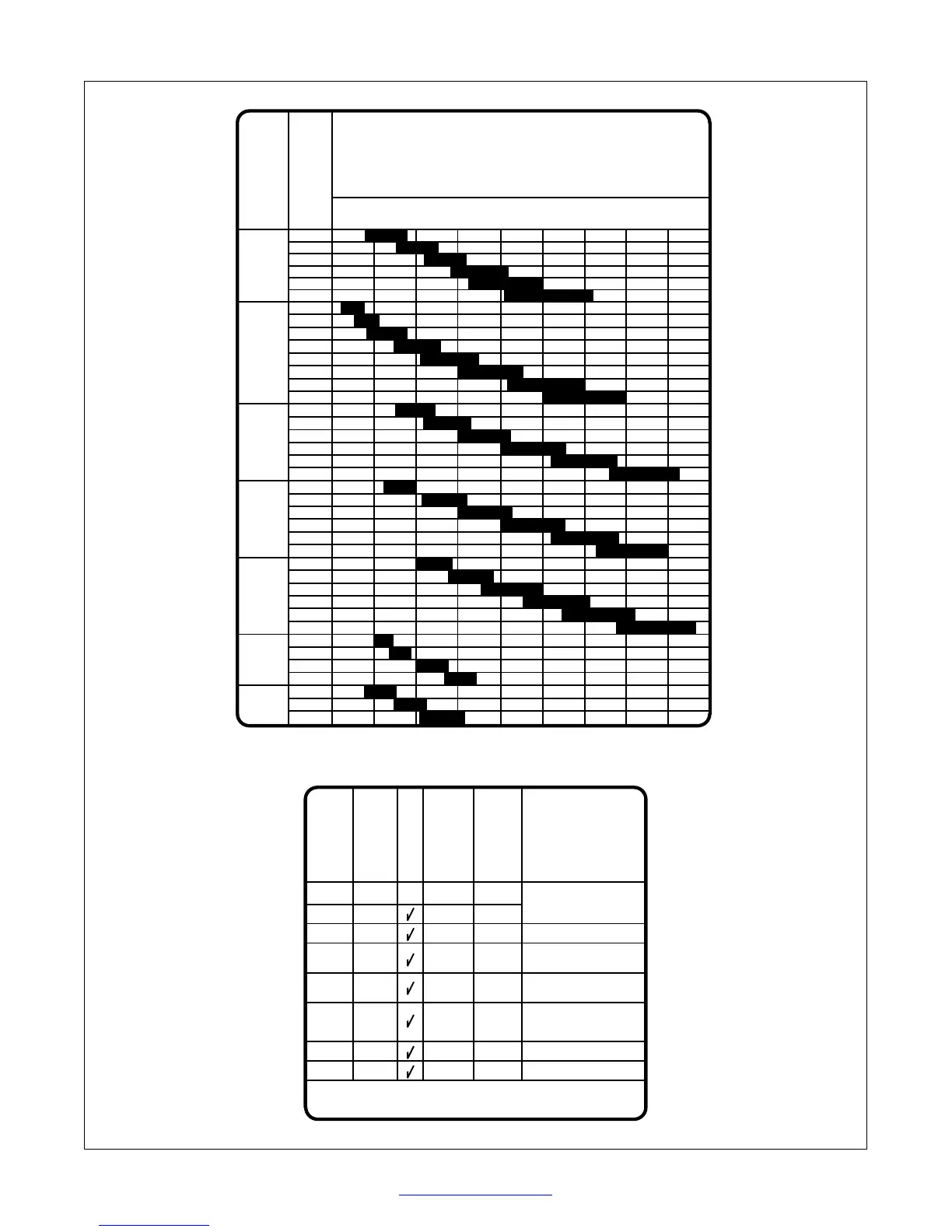
Ask a question
Hobart STICKMATE LX Specifications
General
Input Voltage
230 V
Input Phase
Single Phase
Input Frequency
50/60 Hz
Welding Process
Stick (SMAW)
Type
Stick Welder
Electrode Size Range
1/16 in to 5/32 in
Related product manuals
Hobart Stickmate 160i
40 pages
Hobart 210 MVP
44 pages
Hobart Handler 210
56 pages
Hobart Handler 140
48 pages
Hobart Handler 190
44 pages
Hobart Handler 125
52 pages
Hobart IronMan 240
48 pages
Hobart Handler 135
48 pages
Hobart Champion 145
48 pages
Hobart AirForce 400
32 pages
Hobart Plasma Cutter
2 pages
Hobart Handler 125 EZ
48 pages