OM-316 Page 18
Return To Table Of Contents
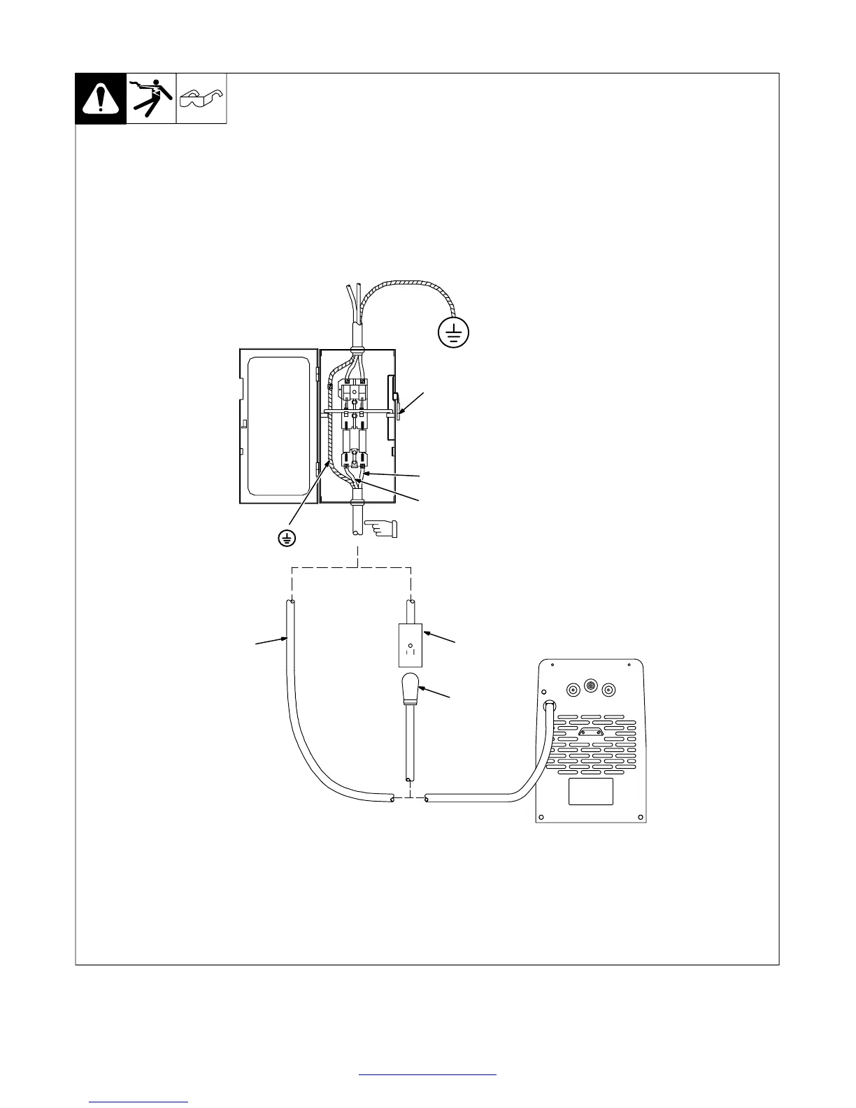
3-10. Connecting Input Power
ST-802 246
Y Disconnect and lockout/tag-
out input power before con-
necting input conductors
from unit.
Y Have only qualified persons
make this installation. See
rating label in Section 3-4, and
be sure to supply correct in-
put power.
1 Line Disconnect Device
2 Input And Grounding
Conductors For Models Not
Supplied With Plug
See Section 3-7 for conductor and
fuse size and ratings. Size and
ratings must comply with applicable
codes.
3 Plug
4 Proper Receptacle
(User-Supplied)
GND/PE
L1
2
3
Install conductors into a deenergized line
disconnect device.
Y Always connect
grounding
conductor first.
4
L2
1

 Loading...