86
7. Installation of electrical devices
Battery charger
j
in the clothes cupboard
1
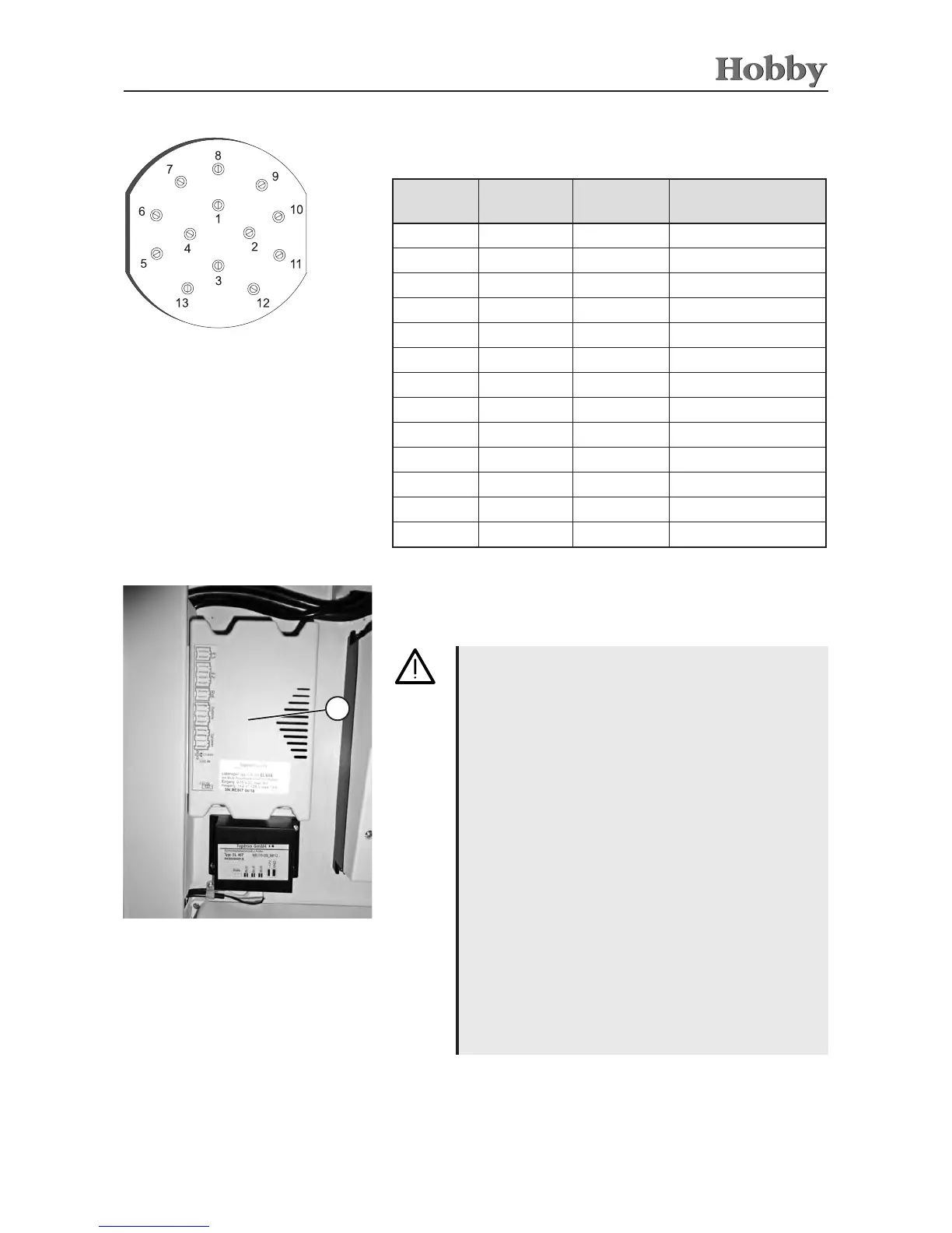
Connector pins on 13-pole plug
("Jäger" system)
Connector pin assignment of the 13-pole plug
(„Jäger“ outlet)
PIN Colour of
conductor
Cross
section
Electrical
devices
1 yellow 1,5 Left blinker
2 blue 1,5 Fog tail lamp
3 white 2,5 Mass (1-8)
4 green 1,5 Right blinker
5 brown 1,5 Right light
6 red 1,5 Brake light
7 black 1,5 Left light
8 orange 1,5 Back-up light
9 blue 2,5 Steady plus
10 blue/white 2,5 'Plus' ignition
11 white/red 2,5 Mass (10)
12 violet 1,5 Camper licence plate
13 white/blue 2,5 Mass (9)
Operation via auxiliary battery*
(self-sucient package)
• Onlyaccumulatorbatterieswithboundelectrolytes
(gelorAGMbatteries)maybeinstalledinthosepo-
sitionsspeciedbythemanufacturer.
•Theinstalledbatterymaynotbeopened.
• Whenchangingauxiliarybatteries,useonlybatteries
ofthesamemakeandcapacity.
(Settingthebatterytypeonthecontrolpanel:
see p. 72)
•Beforedisconnectingorconnectingtheauxiliary
battery, disconnect the electric connection to the
basevehicleandswitchothe230Vsupply,the12
Vsupplyaswellasallelectricaldevices.
• Beforereplacingfusesyoumustrst de-energise
the charge controller.
• Beforereplacingablownfuseyoumustrstx
whatever caused the fuse to blow.
• Fusesmayonlybereplacedbyfuseswiththesame
fuseprotectionvalue.
• Airingthechargecontrollerinsucientlywillcausea
reduction of the charge current.
•Thesurfaceofthechargecontrollercasingmaybe-
comehotwhenthedeviceisinoperation.