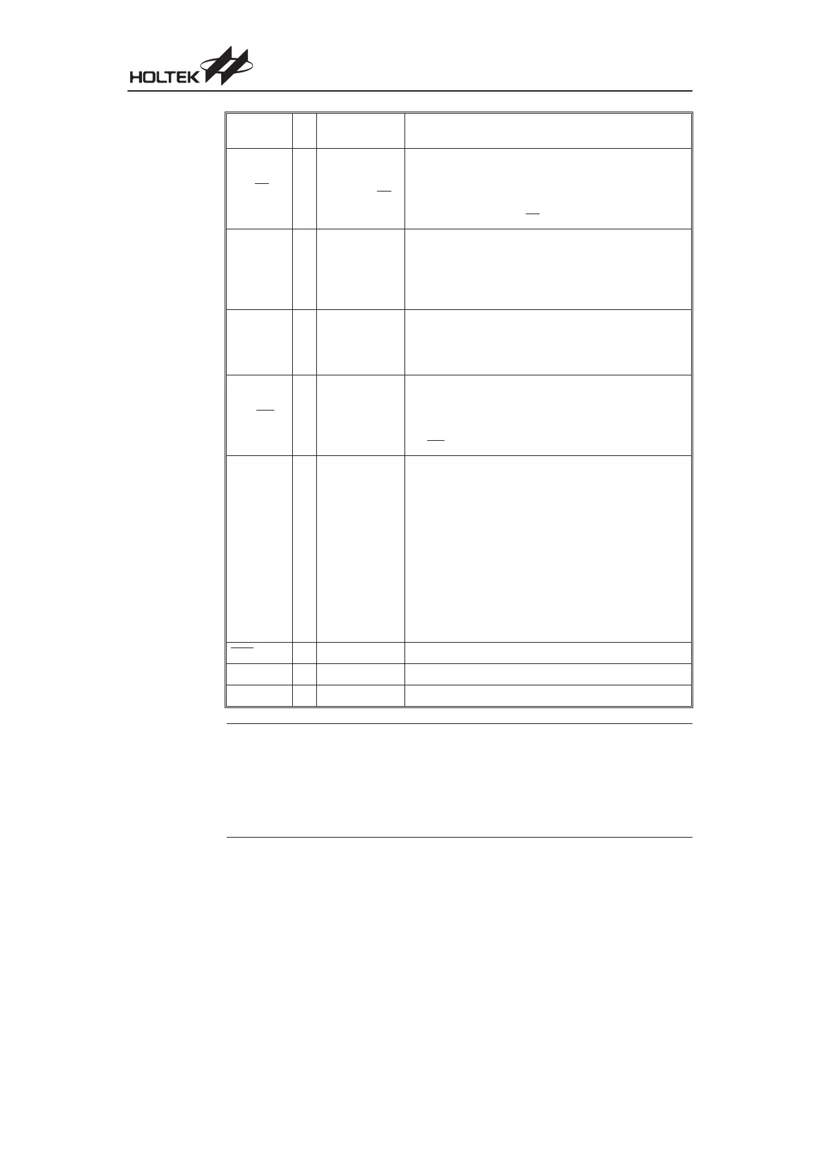
Pin Name I/O
Configuration
Option
Description
PB0/BZ
PB1/BZ
PB2~PB7
I/O
Pull-high
I/O or BZ/BZ
Bidirectional 8-bit input/output port. Software instructions
determine if the pin is a CMOS output or Schmitt Trigger
input. A configuration option determines if all pins on this
port have pull-high resistors. Pins PB0 and PB1 are
pin-shared with BZ and BZ
, respectively.
PC0/TMR0
PC5/TMR1
PC1~PC4
PC6~PC7
I/O Pull-high
Bidirectional 8-bit input/output port. Software instructions
determine if the pin is a CMOS output or Schmitt Trigger in
-
put. A configuration option determines if all pins on this port
have pull-high resistors. TMR0 and TMR1 are pin-shared
with PC0 and PC5 respectively in the 28-pin package.
PD0~PD7 I/O Pull-high
Bidirectional 8-bit input/output port. Software instructions
determine if the pin is a CMOS output or Schmitt Trigger
input. Configuration options determine if all pins on this
port have pull-high resistors.
PG0/INT I/O Pull-high
Bidirectional 1-bit input/output ports. Software instructions
determine if the pin is a CMOS output or Schmitt Trigger
input. A configuration option determines if the pin has a
pull-high resistor. PG0 is pin-shared with external interrupt
pin INT
.
OSC1/PG1
OSC2/PG2
I
O
Pull-high
Crystal or RC or
Int. RC+I/O or
Int. RC+RTC
OSC1, OSC2 are connected to an external RC network or
external Crystal (determined by configuration option) for
the internal system clock. For external RC system clock
operation, OSC2 is an output pin for 1
/
4 system clock.
These two pins can also be optioned as an RTC oscillator
(32768Hz) or I/O lines. In these two cases, the system
clock comes from an internal RC oscillator whose nominal
frequency at 5V has 4 options, 3.2MHz, 1.6MHz, 800kHz,
400kHz. If the pins are used as normal I/O pins, then
pull-high options are available. If used as oscillator pins,
bits PG1 and PG2 will be free for use by the application
program. In this case the pull-high options are disabled.
RES I
¾
Schmitt Trigger reset input. Active low.
VDD
¾¾
Positive power supply
VSS
¾¾
Negative power supply, ground
Note 1. Each pin on PA can be programmed through a configuration option to have a wake-up function.
2. Individual pins cannot be selected to have pull-high resistors. If the pull-high configuration is
chosen for a particular port, then all input pins on this port will be connected to pull-high resistors.
3. On the 48-pin package Port C has no shared pins. All of Port C pins exist as I/Os as the TMR0
and TMR1 are independent pins.
4. Pins PC6 and PC7 only exist on the 48-pin package.
5. Port D is only present on the 48-pin package.
Chapter 1 Hardware Structure
11
 Loading...
