Configuring the Pulse Width Measurement Mode
In this mode, the width of external pulses applied to the external timer pin can be measured. In the
Pulse Width Measurement Mode the timer clock source is supplied by the internal clock. For the
timer to operate in this mode, the bit pair, TM1/TM0, T0M1/T0M0, T1M1/T1M0 or T2M1/T2M0, de
-
pending upon which timer is used, must both be set high. Depending upon which counter is used,
if TE, T0E, T1E or T2E is low, once a high to low transition has been received on the external timer
pin, the timer will start counting until the external timer pin returns to its original high level. At this
point the TON, T0ON, T1ON or T2ON bit, depending upon which counter is used, will be automati
-
cally reset to zero and the timer will stop counting. If the TE, T0E, T1E or T2E bit is high, the timer
will begin counting once a low to high transition has been received on the external timer pin and
stop counting when the external timer pin returns to its original low level. As before, the TON,
T0ON, T1ON or T2ON bit will be automatically reset to zero and the timer will stop counting. It is im
-
portant to note that in the Pulse Width Measurement Mode, the TON, T0ON, T1ON or T2ON bit is
automatically reset to zero when the external control signal on the external timer pin returns to its
original level, whereas in the other two modes the TON, T0ON, T1ON or T2ON bit can only be re
-
set to zero under program control. The residual value in the timer, which can now be read by the
program, therefore represents the length of the pulse received on the external timer pin. As the
TON, T0ON, T1ON or T2ON bit has now been reset, any further transitions on the external timer
pin, will be ignored. Not until the TON, T0ON, T1ON or T2ON bit is again set high by the program
can the timer begin further pulse width measurements. In this way, single shot pulse measure-
ments can be easily made. It should be noted that in this mode the counter is controlled by logical
transitions on the external timer pin and not by the logic level.
As in the case of the other two modes, when the counter is full, the timer will overflow and generate
an internal interrupt signal. The counter will also be reset to the value already loaded into the
preload register. If the external timer pin is pin-shared with other I/O pins, to ensure that the pin is
configured to operate as a pulse width measuring input pin, two things have to happen. The first is
to ensure that the TM1/TM0, T0M1/T0M0, T1M1/T1M0 or T2M1/T2M0 bits place the Timer/Event
Counter in the pulse width measuring mode, the second is to ensure that the port control register
configures the pin as an input. It should be noted that a timer overflow is one of the interrupt and
wake-up sources.
48
I/O Type MCU
T i m e r + 2 T i m e r + 3
E x t e r n a l E v e n t
I n c r e m e n t
T i m e r C o u n t e r
T i m e r + 1
Event Counter Mode Timing Chart
+ 1 + 2 + 3 + 4
T i m e r
E x t e r n a l T i m e r
P i n I n p u t
T O N , T 0 O N , T 1 O N o r T 2 O N
( w i t h T E , T 0 E , T 1 E o r T 2 E = 0 )
P r e s c a l e r O u t p u t
( w i t h c l o c k = f
S Y S
)
I n c r e m e n t
T i m e r C o u n t e r
P r e s c a l e r o u t p u t i s s a m p l e d a t e v e r y f a l l i n g e d g e o f T 1 .
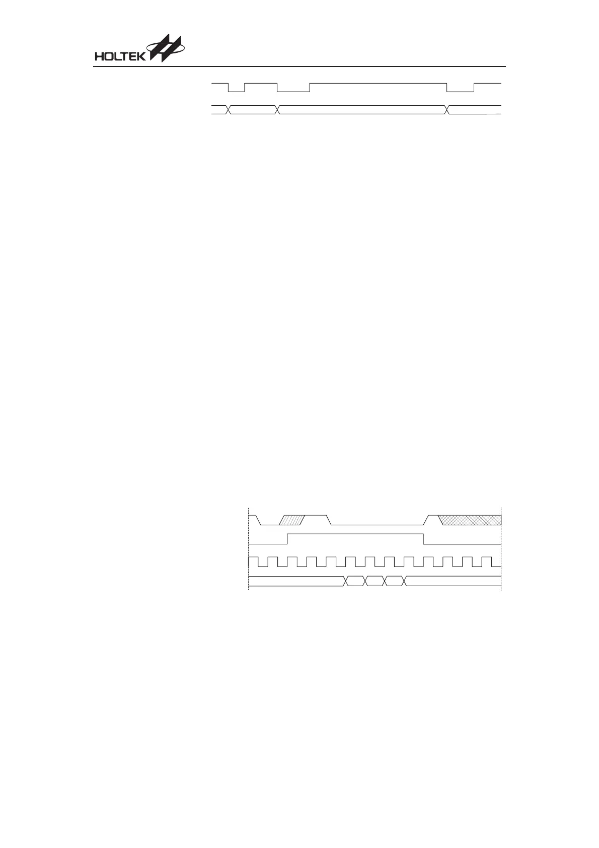
Pulse Width Measurement Mode Timing Chart
 Loading...
