OSC1 and OSC2 pins are free for use as normal I/O pins. The OSC1 and OSC2 pins can also be
connected to a 32768Hz crystal for use as an RTC oscillator on all devices. If the RTC oscillator is
to be used in user applications, the internal RC oscillator must be used as the system clock. Note
that the oscillation frequency of this internal system RC oscillator can vary with VDD, temperature
and process variations.
RTC Oscillator
When microcontrollers enter a power down or HALT condition, the system clock is switched off to
stop microcontroller activity and to conserve power. However, in many microcontroller applica
-
tions it may be necessary to keep the internal timers operational even when the microcontroller is
in a HALT state. However, to do this, another clock, independent of the system clock, must be pro
-
vided. To provide this feature, all of Holtek¢s I/O range of microcontrollers incorporate a Real Time
Clock or RTC. This clock source has a fixed frequency of 32768Hz and requires a 32768Hz crystal
to be connected between pins OSC1 and OSC2. For applications using the RTC oscillator, the in
-
ternal RC Oscillator must be used as the system clock. Oscillator configuration options determine
if the RTC is to be used. If the RTC oscillator configuration option is selected, then the timer(s)
have the configuration option of selecting either the internal RC system clock or RTC as their clock
source.
The RTC, if selected as the clock source for the timers, allows the timer functions to remain active
even if the microcontroller is in the Power Down Mode and as such will issue the usual internal inter-
rupt signal when the counter is full. This signal will cause the microcontroller to wake-up from its
HALT state and continue with normal operation until the next ²HALT² instruction is executed.
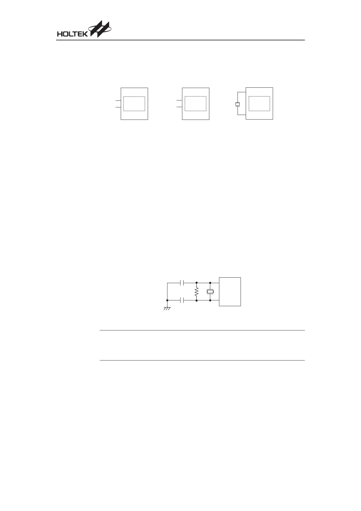
Note
The external resistor and capacitor components connected to the 32768Hz crystal are not neces
-
sary to provide oscillation. For applications where precise RTC frequencies are essential, these
components may be required to provide frequency compensation due to different crystal manu
-
facturing tolerances. In some applications only capacitor C1 is required.
Chapter 1 Hardware Structure
85
·
I n t e r n a l R C
S y s t e m O s c i l l a t o r
·
R T C 3 2 7 6 8 H z C r y s t a l
C o n n e c t e d t o O s c i l l a t o r P i n s
·
A p p l i c a b l e t o a l l D e v i c e s
O S C 2
O S C 1
·
I n t e r n a l R C
S y s t e m O s c i l l a t o r f o r
H T 4 8 R 3 0 A - 1 / H T 4 8 C 3 0 - 1 a n d
H T 4 8 R 5 0 A - 1 / H T 4 8 C 5 0 - 1
·
O s c i l l a t o r P i n s U s e d a s I / O s
·
I n t e r n a l R C
S y s t e m O s c i l l a t o r f o r
H T 4 8 R 1 0 A - 1 / H T 4 8 C 1 0 - 1
·
O s c i l l a t o r P i n s U s e d a s I / O s
P C 4
( O S C 2 )
P C 3
( O S C 1 )
I n t e r n a l R C
O s c i l l a t o r
P G 2
( O S C 2 )
P G 1
( O S C 1 )
R T C
3 2 7 6 8 H z
C r y s t a l
I n t e r n a l R C
O s c i l l a t o r
I n t e r n a l R C
O s c i l l a t o r
O S C 2
O S C 1
C 2
C 1
R 1
3 2 7 6 8 H z
RTC Oscillator
 Loading...
