Timer/Event Counters
The provision of timers form an important part of any microcontroller, giving the designer a means
of carrying out time related functions. The devices in the I/O Type MCU series contain either one,
two or three count up timers of either 8 or 16-bit capacity depending upon which device is se
-
lected. As each timer has three different operating modes, they can be configured to operate as a
general timer, an external event counter or as a pulse width measurement device. The provision of
an internal prescaler to the clock circuitry of some of the timer/event counters gives added range
to the timer.
There are two types of registers related to the Timer/Event Counters. The first is the register that
contains the actual value of the timer and into which an initial value can be preloaded. Reading
from this register retrieves the contents of the Timer/Event Counter. The second type of associ
-
ated register is the timer control register which defines the timer options and determines how the
timer is to be used. All devices can have the timer clock configured to come from the internal clock
source. In addition, the timer clock source can also be configured to come from an external timer
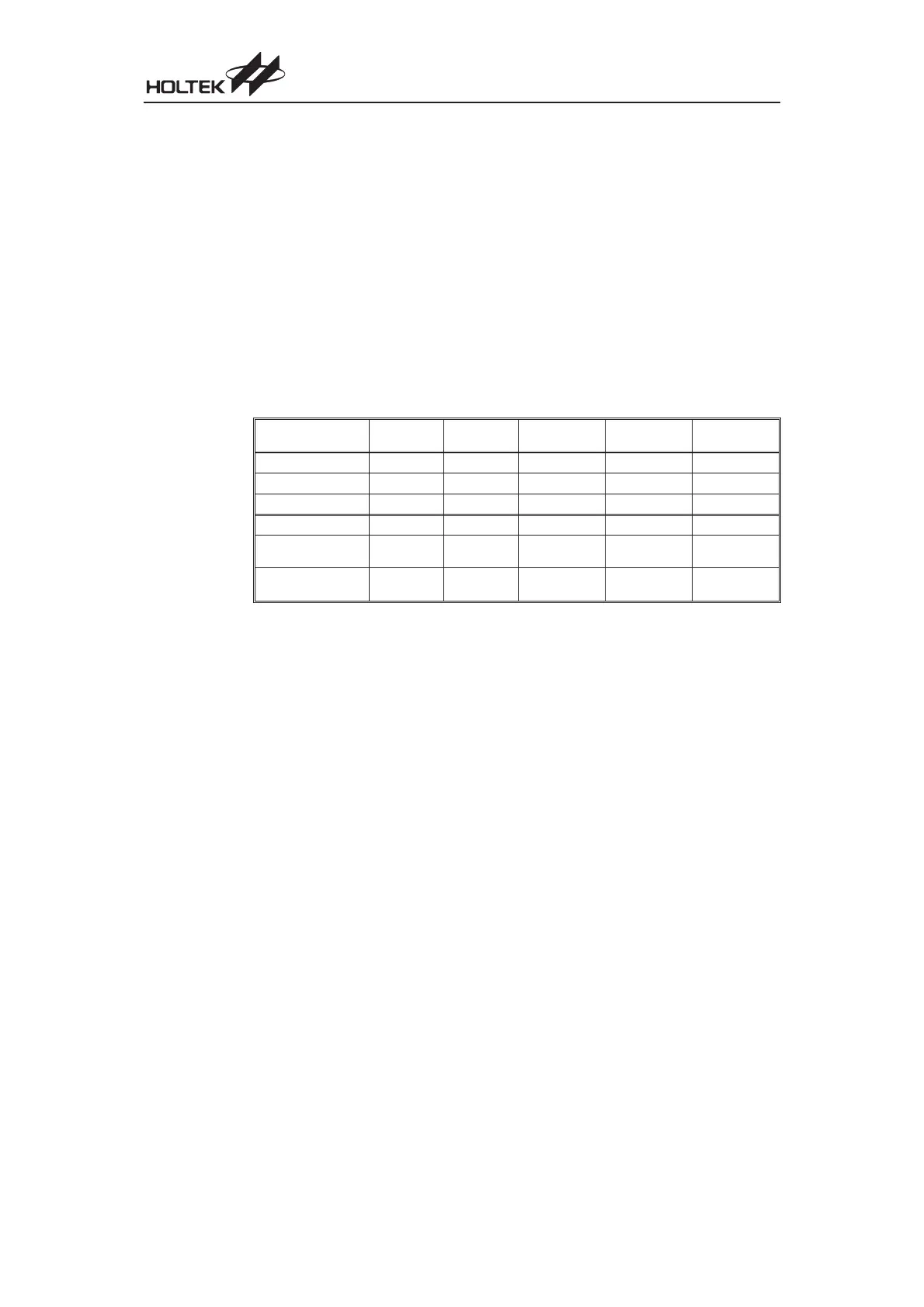
pin. The accompanying table lists the associated timer register names.
HT48R10A-1
HT48C10-1
HT48R30A-1
HT48C30-1
HT48R50A-1
HT48C50-1
HT48R70A-1
HT48C70-1
HT48RU80
HT48CU80
No. of 8-bit Timers 11101
Timer Register Name
TMR TMR
TMR0
¾
TMR2
Timer Control Register
TMRC TMRC
TMR0C
¾
TMR2C
No. of 16-bit Timers 00122
Timer Register Name
¾¾
TMR1L/TMR1H
TMR0L/TMR0H
TMR1L/TMR1H
TMR0L/TMR0H
TMR1L/TMR1H
Timer Control Register
¾¾
TMR1C
TMR0C
TMR1C
TMR0C
TMR1C
An external clock source is used when the timer is in the event counting mode, the clock source be-
ing provided on the external timer pin known as TMR, TMR0, TMR1 or TMR2 depending on which
device is selected. These external pins may be pin-shared with other I/O pins depending upon
which device and package is chosen. Depending upon the condition of the TE, T0E, T1E or T2E
bit in the corresponding timer control register, each high to low, or low to high transition on the ex-
ternal timer input pin will increment the counter by one.
Configuring the Timer/Event Counter Input Clock Source
The internal timer¢s clock can originate from various sources, depending upon which device and
which timer is chosen. The system clock input timer source is used when the timer is in the timer
mode or in the pulse width measurement mode. Depending upon which timer and which device is
chosen this system clock timer source may be first divided by a prescaler, the division ratio of
which is conditioned by the timer control register bits PSC2~PSC0, T0PSC2~T0PSC0 or
T2PSC2~T2PSC0.
An external clock source is used when the timer is in the event counting mode, the clock source be
-
ing provided on an external timer pin, TMR, TMR0, TMR1 or TMR2 depending upon which device
and which timer is used. Depending upon the condition of the TE, T0E, T1E or T2E bit, each high
to low, or low to high transition on the external timer pin will increment the counter by one.
Chapter 1 Hardware Structure
41