UART Sample Program
The following application program shows how the UART can be used for the transmission and re
-
ception of external data:
t_uart_TX:
clr intc0 ; disable intc0
clr intc1 ; disable intc1
mov a,80h
mov ucr1,a ; enable uarten
mov brg,a ; set brg=80H
mov ucr2,a ; enable txen
mov a,055h
mov txr,a ; set txr=55H
:
:
jmp t_uart_TX
t_uart_RX:
clr intc0 ; disable intc0
clr intc1 ; disable intc1
mov a,80h
mov ucr1,a ; enable uarten
mov brg,a ; set brg=80H
mov a,40h
mov ucr2,a ; enable rxen
mov a,rxr
mov pa,a ; pa=rxr
:
:
jmp t_uart_RX
Oscillator
Various oscillator options offer the user a wide range of functions according to their various applica-
tion requirements. Three types of system clocks can be selected while various clock source op-
tions for the Watchdog Timer as well as a real time clock function are provided for maximum
flexibility. All oscillator options are selected through the configuration options.
System Clock Configurations
There are three methods of generating the system clock, using an external crystal/ceramic oscilla-
tor, an external RC network or using the internal RC clock source. The chosen method is selected
through the configuration options.
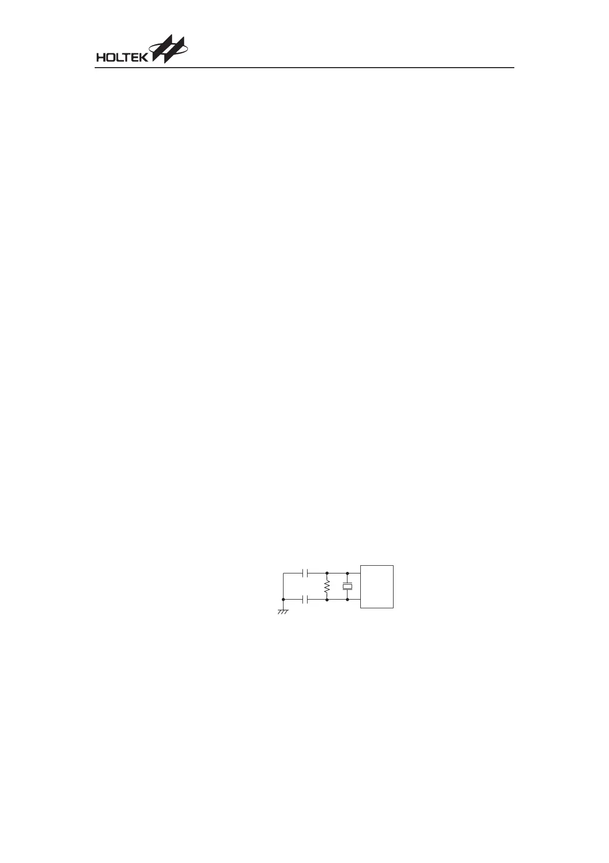
System Crystal/Ceramic Oscillator
For most crystal oscillator configurations, the simple connection of a crystal across OSC1 and
OSC2 will create the necessary phase shift and feedback for oscillation. However, to ensure oscil
-
lation for certain lower crystal frequencies and for all ceramic resonator applications, it is recom
-
mended that two small value capacitors and a resistor, the values of which are shown in the table,
should be connected as shown in the diagram.
Chapter 1 Hardware Structure
83
O S C 2
O S C 1
C 2
C 1
R 1
Crystal/Ceramic Oscillator