memory address, a power-on reset also ensures that certain other registers are preset to known
conditions. All the I/O port and port control registers will power-up in a high condition ensuring that
all pins will be first set to inputs.
Although the microcontroller has an internal RC reset function, due to unstable power-on condi
-
tions, an external RC network connected to the RES
pin is generally recommended. This time de
-
lay created by the RC network ensures that the RES
pin remains low for an extended period while
the power supply stabilizes. During this time, normal operation of the microcontroller is inhibited.
After the RES
line reaches a certain voltage value, the reset delay time t
RSTD
is invoked to provide
an extra delay time after which the microcontroller can begin normal operation. The abbreviation
SST in the figures stands for System Start-up Timer.
RES
Pin Reset
This type of reset occurs when the microcontroller is already running and the RES
pin is forcefully
pulled low by external hardware such as an external switch. In this case as in the case of other re
-
set, the Program Counter will reset to zero and program execution initiated from this point.
Low Voltage Reset - LVR
The microcontroller contains a low voltage reset circuit in order to monitor the supply voltage of the
device. If the supply voltage of the device drops to within a range of 0.9V~V
LVR
such as might occur
when changing the battery, the LVR will automatically reset the device internally. The LVR includes
the following specifications: For a valid LVR signal, a low voltage, i.e. a voltage in the range be
-
tween 0.9V~V
LVR
must exist for greater than 1ms. If the low voltage state does not exceed 1ms,
the LVR will ignore it and will not perform a reset function.
Chapter 1 Hardware Structure
59
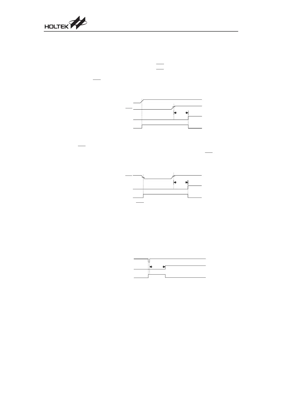
R E S
S S T T i m e - o u t
I n t e r n a l R e s e t
0 . 9 V
D D
0 . 4 V
D D
t
R S T D
RES Reset Timing Chart
L V R
S S T T i m e - o u t
I n t e r n a l R e s e t
t
R S T D
Low Voltage Reset Timing Chart
R E S
V D D
S S T T i m e - o u t
I n t e r n a l R e s e t
0 . 9 V
D D
t
R S T D
Power-On Reset Timing Chart