OPERATION
HOLZMANN Maschinen Austria www.holzmann-maschinen.at Seite 52
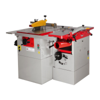
5-fach Kombination / combined 5-operation machine K5 260L
- If the workpiece is no longer moved by the automatic feed, pull the workpiece manually.
- Off after crimp machine with stop button and lever for feed (D) to position "OFF".
Before other activities to wait until planer stands still!
For dressing, the machine must be dismantled mutatis mutandis wrong
14.6 Milling
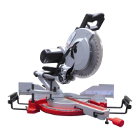
14.6.1 Changing the milling head
Switch off the machine
Secure the end cap with a 22mm Allen key
Use an Allen wrench to remove the screw from the spindle 8mm
remove.
Remove the cutting head and replace these by the appropriate.
Set a distance from the table top from at least 2mm clearance.
Install the milling tools as low as possible.
Select to match the height of the milling tool, so that it at least 2mm
is over the spindle top. Insert the end cap (E).
Now screw in the allen screw and tighten it firmly on the spindle.
3. Mount spindle shapper protection as in 13.2.4
4. Spindle height as set in 14.6.2
Check immediately after mounting the free run of the mill.
NOTES
- Beware material setback! To minimize the danger of material setback, they put the hold-
down on Workpiece height + max. 2mm one.
- Set spindle shapper protection on the workpiece width + max 5mm one.
- Run the workpiece to be slow and constant.
- You never Milling (except for some special cases, but they require the experience of the user)
to the direction of rotation of the milling cutter.
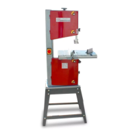
14.6.2 Setting of the milling spindle height
ATTENTION: Perform the setting of the milling spindle height by
only with the machine switched off.
By clockwise rotation, the spindle moves down. Turn counterclock-
wise to top.
The set height can be fixed by the clamping screw (A).


 To Next Page