11. TRANSMISSION
SERVICE INFORMATION 11-1
INVESTIGATION OF FAULTS 11-2
SEPARATION OF THE CASING OF THE ENGINE
11-3
DISASSEMBLY OF THE THE TRANSMISSION 11 4
ASSEMBLY OF THE TRANSMISSION 11-8
ASSEMBLY OF THE CASING OF THE ENGINE11-11
CBX250
SERVICE INFORMATION
GENERAL INSTRUCTIONS
•In this section describes procedures of transmission service, even the forks, the drum selector and the spindle of
changing gears. Refer to Section 12 to obtain information in respect of services in the crankshaft and flywheel. •The
casing of the engine is must remove provided they are effected services of repair and maintenance in the trans-
mission. For those services must remove the engine of chassis (Section 6). •Remove the following components before
separating the casing of the engine: Cylinder head (Section 7) Cylinder and piston (Section 8) Clutch, gear primary command
and selector gears (section 9) oil pump (Section 4) engine Flywheel (Section 10) • Be careful not to damage the
contact surfaces of the casing of the engine to make the service.
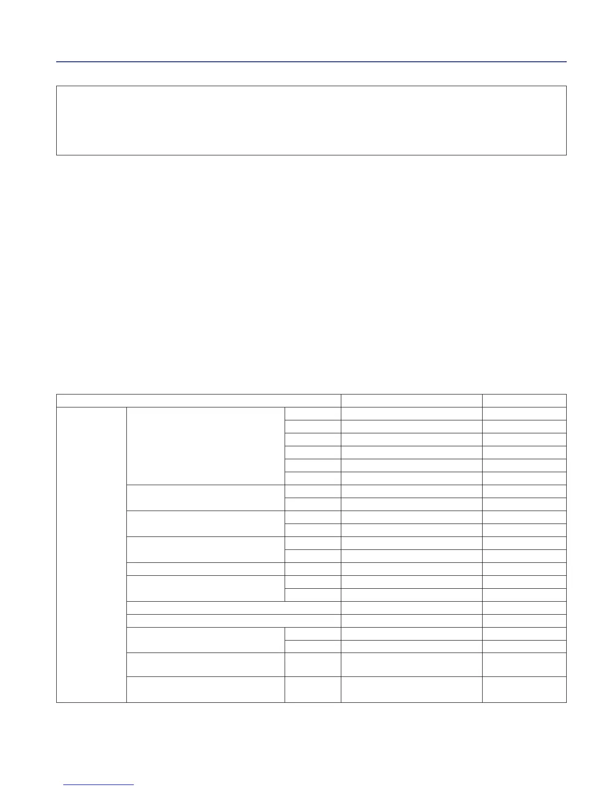
SPECIFICATIONS
Unit: mm
Item Value Service Limit
Transmission D. I. gear M5 20,000 – 20,021 20,08
M6 23,000 – 23,021 23,07
C1 23,000 – 23,021 23,07
C2 25,020 – 25,041 25,09
C3 25,000 – 25,021 25,07
C4 22,000 – 22,021 22,07
D. E. of the hub of gear C1 22,959 – 22,980 22,90
C2 24,979 – 25,000 24,90
D. I. the hub of gear C1 18,000 – 18,018 18,08
C2 22,000 – 22,021 22,08
D. E. spacer C3 24,959 – 24,980 24,90
M6 22,959 – 22,980 22,92
D. E. of the main axle al M5 19,959 – 19,980 19,91
D. E. of countershaft al C1 17,966 – 17,984 17,91
al C2, C4 21,959 – 21,980 21,91
Slack between gear and the hub 0,020 – 0,062 0,10
Slack between gear and the spacer 0,020 – 0,062 0,10
Slack between the axle and the hub C1 0,016 – 0,052 0,10
C2 0,020 – 0,062 0,10
Slack between the gear and the
al M5 0,020 – 0,062 0,10
main axle
Slack between gear and
al C4 0,020 – 0,062 0,10
the countershaft
 Loading...