FUEL SYSTEM (PGM-FI)
5-18
DTC TROUBLESHOOTING
DTC 1-1 (MAP SENSOR LOW
VOLTAGE)
• Before starting the inspection, check for loose or
poor contact on the MAP sensor 3P (Black) con-
nector and ECM 33P connectors, then recheck
the DTC.
1. MAP Sensor System Inspection
Turn the ignition switch ON and engine stop
switch " ".
Check the MAP sensor with the HDS.
Is about 0 V indicated?
YES – GO TO STEP 2.
NO – Intermittent failure
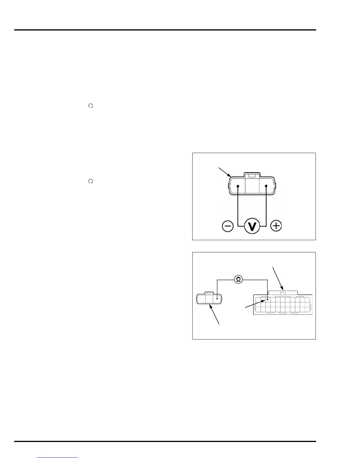
2. MAP Sensor Input Voltage Inspection
Turn the ignition switch OFF.
Disconnect the MAP sensor 3P (Black) connec-
tor.
Turn the ignition switch ON and engine stop
switch " ".
Measure the voltage at the wire harness side.
Is the voltage within 4.75 – 5.25V?
YES – GO TO STEP 4.
NO – GO TO STEP 3.
3. MAP Sensor Input Line Inspection
Turn the ignition switch OFF.
Disconnect the ECM 33P (Black) connector.
Check for continuity between the MAP sensor 3P
(Black) connector and ECM 33P (Black) connec-
tor.
Is there continuity?
YES – Replace the ECM with a new one, and
recheck; for Key Registration Proce-
dures (page 21-4).
NO – Open circuit in Yellow/red wire
Connection: Yellow/red (+) – Green/orange (–)
MAP SENSOR 3P (BLACK) CONNECTOR
(Wire side/female terminal)
Y/RG/O
Connection: A9 – Yellow/red
TOOL:
Test probe 07ZAJ-RDJA110
ECM 33P (BLACK) CONNECTOR
(Wire side/female terminal)
Y/R
MAP SENSOR 3P (BLACK) CONNECTOR
(Wire side/female terminal)
A9
 Loading...