ANTI-LOCK BRAKE SYSTEM (ABS)
16-24
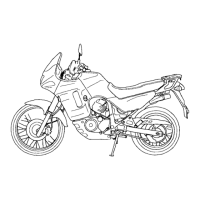
PCV
REMOVAL/INSTALLATION
Drain the brake fluid from the front and rear hydrau-
lic systems (page 15-11).
Remove the battery tray (page 17-6).
Loosen the joint nuts and remove the brake pipe.
Remove the bolts and PCV.
Install the PCV and tighten the bolts securely.
Apply brake fluid to the brake pipe joint nut threads.
Install the brake pipe to the PCV and tighten the
brake pipe joint nuts to the specified torque.
Fill and bleed the hydraulic system (page 15-12).
Install the battery (page 17-6).
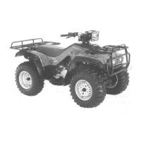
ABS MODULATOR
POWER/GROUND LINE INSPECTION
Remove the left side cover (page 2-4).
Disconnect the ABS modulator 26P connector.
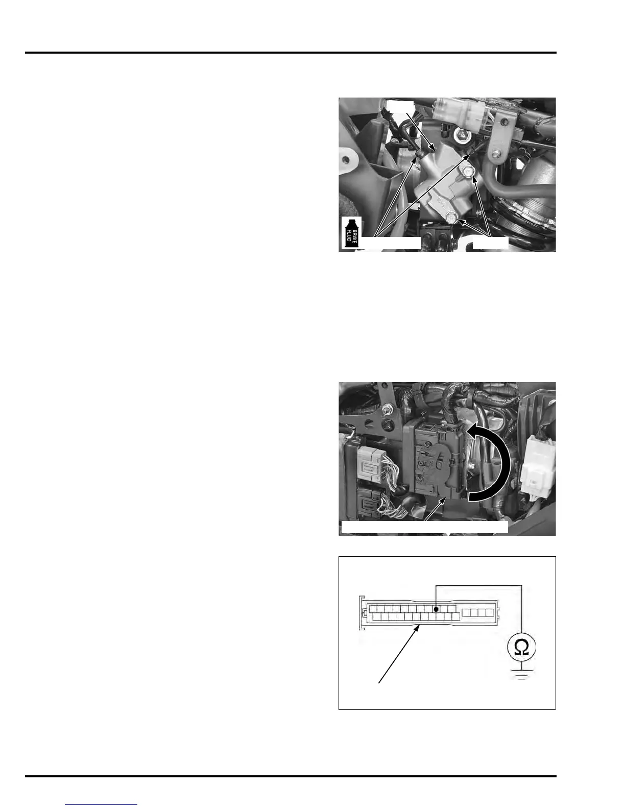
POWER INPUT LINE SHORT CIRCUIT INSPECTION
Measure the continuity between the Red/brown
wire terminals and ground.
There should be no continuity.
If there is continuity, check for open circuit in Red/
brown wires.
When loosening
the brake pipe joint
nuts, cover the end
of the brake pipes
to prevent
contamination.
Be careful not to
bend or damage
the brake pipes
during PCV
removal.
TORQUE: 14 N·m (1.4 kgf·m, 10 lbf·ft)
ABS MODULATOR 26P CONNECTOR
TOOL:
Test probe 07ZAJ-RDJA110
Connection: Red/brown – Ground
R/Br
ABS MODULATOR 26P CONNECTOR
(Wire side/female terminal)
 Loading...