511391 201T User Manual 25
2/07 Honeywell
USER INTERFACE
Address Configuration
Address Configuration
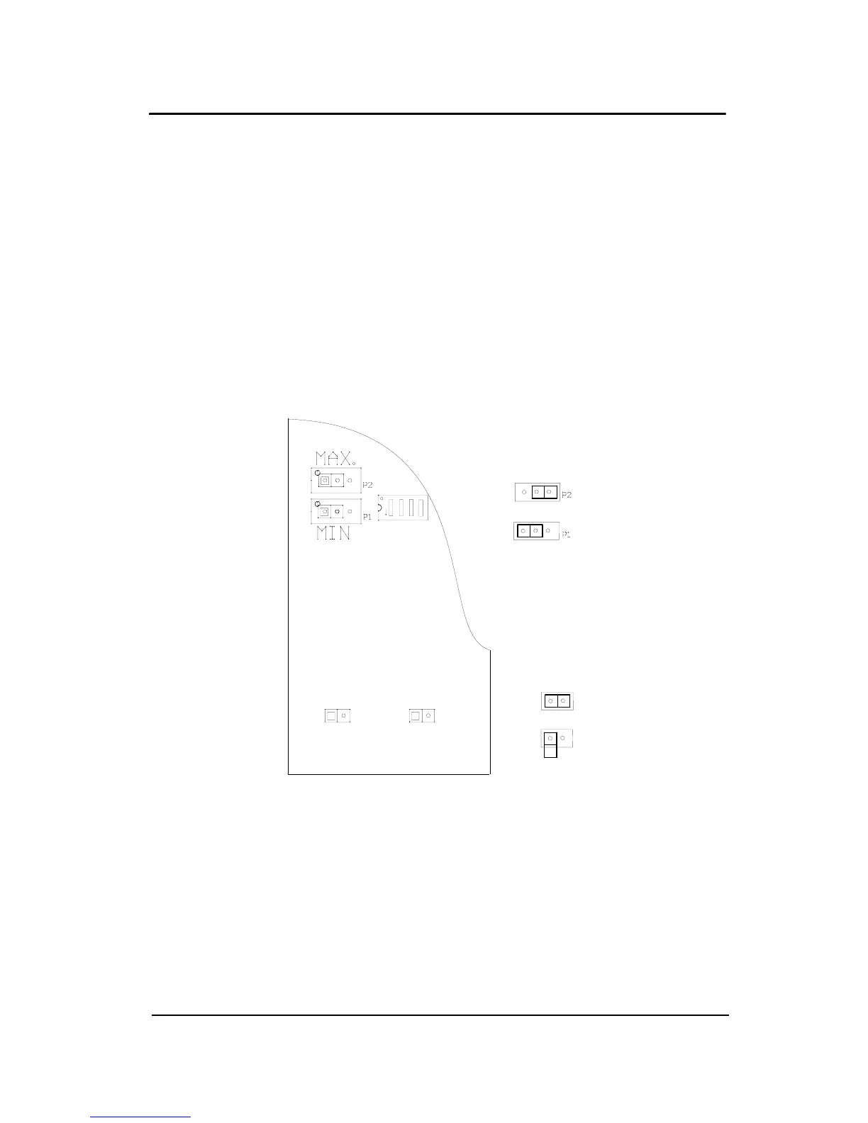
In network mode, the multiple addresses are obtained by varying the
position of the dip switches and various jumpers. Figure below
illustrates the position of these various elements on the PCB. Based on
their configuration, the address will be modified.
The Binary addresses table gives the network addresses with their
corresponding binary addresses. The binary address must be transfer
in the Network vs Binary addresses table where the position of the
different PCB elements will be automatically obtained. The Jumpers
Positions figure illustrates the possible jumpers positions.
Note: If the transmitter is equipped with a display, all values must be
reset to zero. The configuration of the addresses will then be
carried out using the display and keyboard.
12
3
4
ROCKER DOWN
SW2
SW5
ON
OFF
MIN, MAX
Jumper positions
ON
OFF
SW5, SW2
jumper positions
201T PCB: jumpers only
 Loading...