Functional Tests
8500C/8500C+ System Maintenance Manual D-5
D.5.1.3 Balance Test
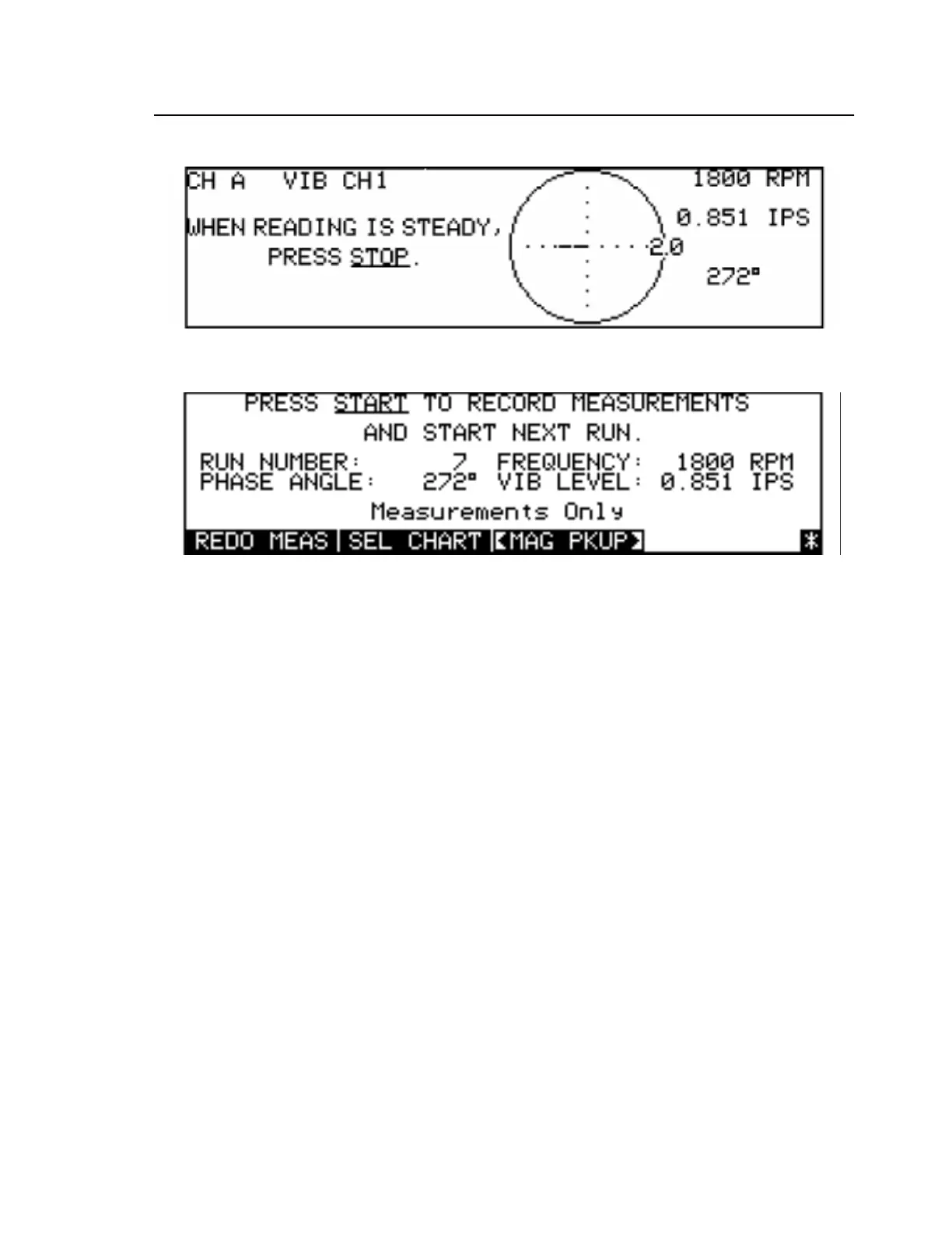
ACQUIRSTION DISPLAY
FINAL RESULTS DISPLAY
Figure D-3. Typical Balance Test Display
a. Ensure that only one No. 6 screw is installed able “h” on the Chadwick-Helmuth logo on
Calibrator 11A rotor disk.
b. Set CAM RATE (RPM) switch on Calibrator 11A to 1800.
c. Adjust pot next to 1800 CAM RATE switch position until outside ring on rotor disk
appears frozen in place under 60 Hz light.
d. Press SETUP key on 8500C/C+.
e. Key in 900 with numberic keys in BALANCE FREQUENCY field.
NOTE: To undo mistaken entries, press the RESTORE soft key.
f. On same line, press right arrow key twice to select last number (called “time factor”) with
arrow keys.
g. Key in 2 as new times factor. This entry now reads: x2.
h. Select AUTO STOP field with arrow keys and press CHANGE soft key to select MAN
STOP.
i. Select PHASE UNITS field with arrow keys.
j. Press CHANGE soft key to select <DEGREES>.
k. Select PICKUP field with arrow keys.
l. Press CHANGE soft key to select PICKUP A.
m. Select INPUT field with arrow keys.
n. Key in <1> with numeric key.
 Loading...


