Detailed Description
8500C/8500C+ System Maintenance Manual 4-13
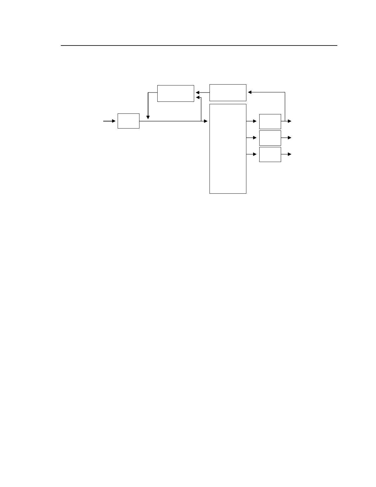
The power supply contains a closed-loop regulator, which keeps the output voltages constant for
varying input voltage and load. An optoisolator feeds back the output voltage across the isolation
barrier. A light emitting diode (LED) indicates when power in on.
Figure 4-7. Power Supply Board Block Diagram (8520C)
4.2.2.4 Quad Peak Detector Board
The quad peak detector board contains four circuits identical to the pulse detector described on the
digital board, one per syn input. Since these circuits are adaptive, this parallel architecture allows rapid
measurement among channels without adaptation latency.
12 TO 28 VDC
DIODE
BRIDGE
REGULATOR/
PWM
STEP-DOWN
TRANSFORMER
OPTO-ISOLATOR/
LED
RECTIFIER/
FILTER
RECTIFIER/
FILTER
RECTIFIER/
FILTER
+5 VDC
+12 VDC
-12 VDC
 Loading...


