Functional Tests
8500C/8500C+ System Maintenance Manual 5-11
.
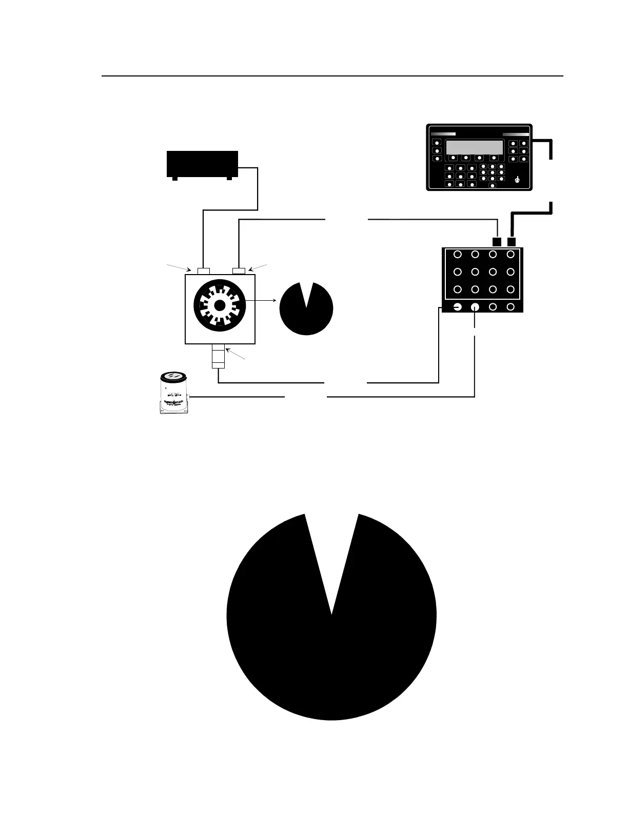
Figure 5-6. Functional Test Setup (with Tracker)
Figure 5-7. Special Overlay
MAG PICKUP 3030
NOTE: The calibrator must have no more than one screw installed on its rotor
disk when used with the 8500C; however, the calibrator was designed to have at
least two screws 180 degrees apart. To simulate a second screw, enter the
actual rpm (half the "CAM RATE") as the balance frequency and "2" as the times
factor in the 8500C balance setup display. For example, if the CAM RATE is
900, enter "450" as the balance frequency and "2" as the times factor.
NOTE: 11B users, bypass
mag pulse doubler and
connect magnetic pickup
cable directly to channel A
on 8520C. This simulates
11A use.
Y
BALANCER/ANALYZER
CHADWICKHELMUTH
E L M O N T E , C A L I F O R N I A
MODEL 8500C
D
J
P
BALANCE
TRACK
#
%
:
SPECTRUM
E
HELP
LOAD
STORE
K
<
Q
>
F
L
R
STATUS
SETUP
-
/
.
PRINT
A
SHOW/HIDE
B
MORE/KEYS
C
STOP
W
Z
X
START
1
4
3
6
G
M
S
7
H
2
N
5
8
T
0
V
I
O
9
U
ANNOTATE
8500C BALANCER/ANALYZER
POWER SUPPLY 9100A
CALIBRATOR 11A
POWER
BALANCER
A
B
CD
2
3
4
5
6
7
8
9
10
11
12
1
CABLE 10808
CABLE 10813
CABLE 10811
CABLE 12700
8520CS SIGNAL SELECTOR
 Loading...


