Functional Tests
8500C/8500C+ System Maintenance Manual D-11
j. Press STATUS key.
k. After a few seconds, the RPM on the screen should read approximately 900 RPM.
NOTE: If you cannot adjust the distance or alignment to obtain 900 RPM, there may be a
problem with the FasTrak. Return it to Chadwick-Helmuth for adjustment.
l. With a white index card or piece of paper, cover half of the rotating disk. Place the card
close to, but not touching, the disk, so as to cover 1/2 Mag Pickup sensor and one vibration
sensor.
m. The RPM should drop by approximately half, remove the card.
Night Mode Test
a. To simulate night operation, turn off all lights in room, or enclose the test setup within a
darkened enclosure, such as a large box. The RPM should drop to zero when the area is
dark enough.
b. Switch Tracker switch to Night mode. (in the cable)
c. After a few seconds, the RPM should appear on the display.
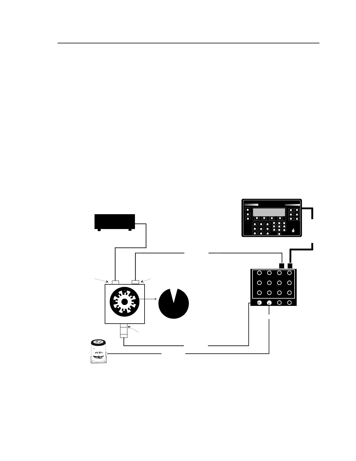
Figure D-5. Functional Test Setup (with Tracker)
MAG PICKUP 3030
NOTE: The calibrator must have no more than one screw installed on its rotor
disk when used with the 8500C; however, the calibrator was designed to have at
least two screws 180 degrees apart. To simulate a second screw, enter the
actual rpm (half the "CAM RATE") as the balance frequency and "2" as the times
factor in the 8500C balance setup display. For example, if the CAM RATE is
900, enter "450" as the balance frequency and "2" as the times factor.
NOTE: 11B users, bypass
mag pulse doubler and
connect magnetic pickup
cable directly to channel A
on 8520C. This simulates
11A use.
Y
BALANCER/ANALYZER
CHADWICK
HELMUTH
E L M O N T E , C A L I F O R N I A
MODEL 8500C
D
J
P
BALANCE
TRACK
#
%
:
SPECTRUM
E
HELP
LOAD
STORE
K
<
Q
>
F
L
R
STATUS
SETUP
-
/
.
PRINT
A
SHOW/HIDE
B
MORE/KEYS
C
STOP
W
Z
X
START
1
4
3
6
G
M
S
7
H
2
N
5
8
T
0
V
I
O
9
U
ANNOTATE
8500C BALANCER/ANALYZER
POWER SUPPLY 9100A
CALIBRATOR 11A
POWER
BALANCER
A
B
CD
2
3
4
5
6
7
8
9
10
11
12
1
CABLE 10808
CABLE 10813
CABLE 10811
CABLE 12700
8520CS SIGNAL SELECTOR
 Loading...


