2-11
2. INSTALLATION
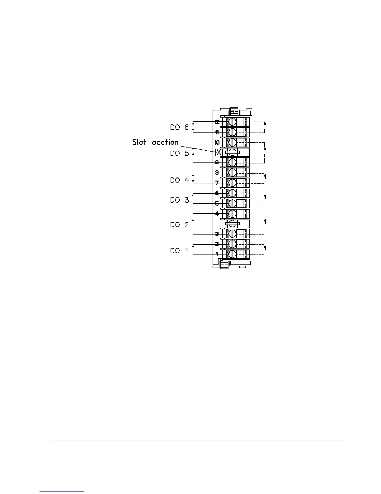
2.5.2 Relay outputs. (DO)
If an optional relay board is installed, connect the wiring as shown in Figure 2-2.
Slot location X = J to P
Figure 2-2 Relay output wiring (DO)
All the relays are factory configured de-energized in alarm. The contacts are factory configured normally
closed by a jumper per output on the alarm relay board.
If you need to change this function for normally opened output:
• Turn off power.
• Remove the rear terminal cover plate and remove the relay board, see page 2-11.
• Move the jumper from the location NC (for normally closed) to the location NO (for normally
opened).
• Up to 36 alarm outputs allowed.
 Loading...