L
Lisa HarrisSep 12, 2025
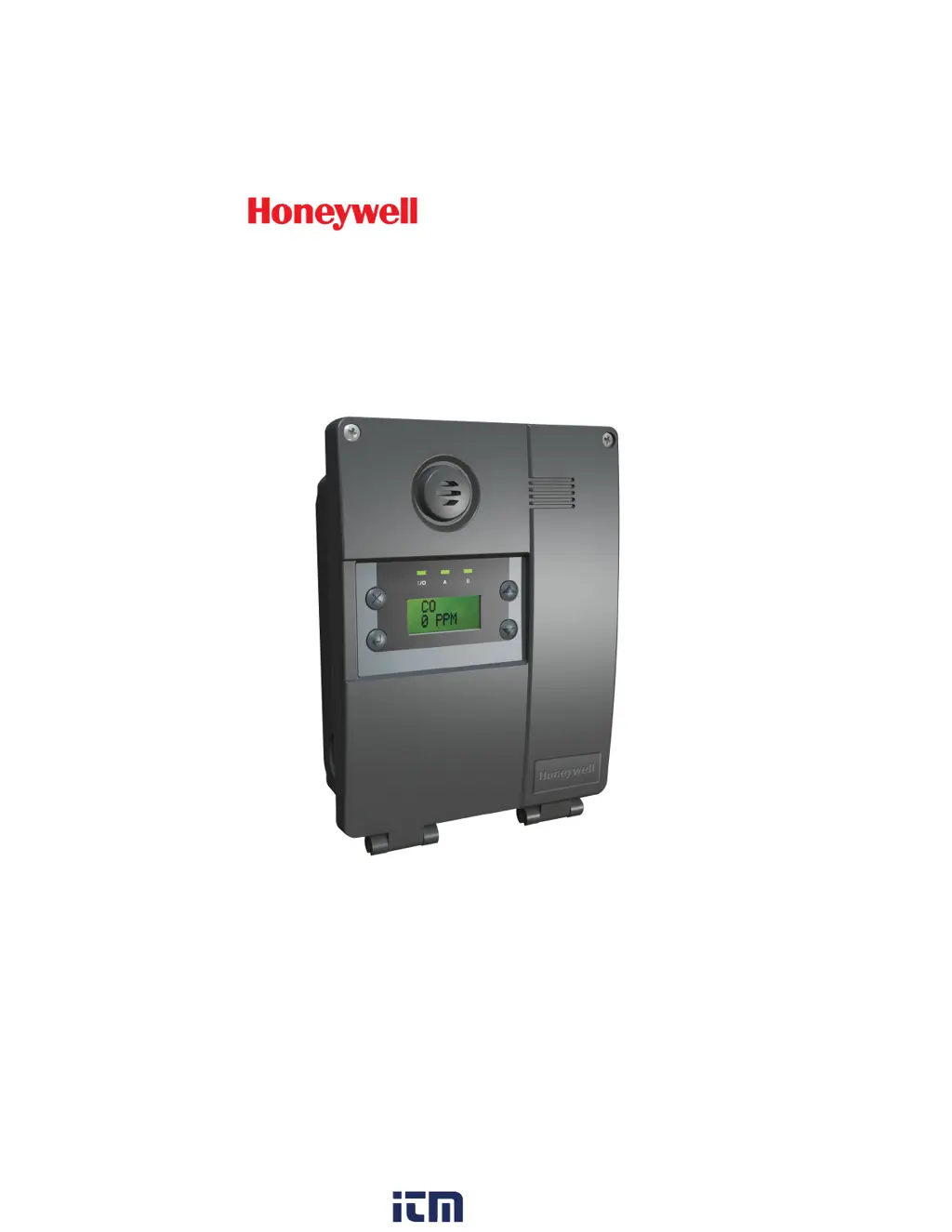
What to do if sensor board eeprom error on Honeywell E3Point E3DA Gas Detectors?
- LlsmithSep 12, 2025
If there is a sensor board eeprom error with your Honeywell Gas Detectors, it is recommended to contact Technical Services.