Excel 800 LION
17 EN1B-0375GE51 R0308
Mounting/Dismounting Modules
WARNING
Risk of electric shock or equipment damage!
►
Do not touch any live parts in the cabinet.
►
Disconnect the power supply before you start to install
the Excel 800 LION System.
More than one disconnect switch may be required to de-
energize the system.
►
Do not reconnect the power supply until you have
completed the installation.
Note
The terminal socket of each I/O module can be mounted
and wired before inserting and locking the corresponding
electronic module.
1
2
3
0
!
A A A
100
LOCK
S1 S2
71 COM a
72 COM b
73 24V~
74 24V0~
21
22
23
14 4424 5434 64 25
13
12
11 31
32
33
41
42
43
51
52
53
61
62
61
62
6363
S1
21
9
GND G
A
V
AUX
10 11 12 13 14 15 16 1 7 1 8
22 1 2 3 4 5 6 7 8
4
87 6 54 32 1 87 65 4 32 1
!
71 COM a
72 COM b
73 24V~
74 24V0~
COM a
COM b
24V~
24V 0~
1:ABCDFERTAQWESDERT1
2:ABCDFERTAQWESD ER T2
3:ABCDFERTAQWESDERT3
4:ABCDFERTAQWESDERT4
5:ABCDFERTAQWESDERT5
6:ABCDFERTAQWESDERT6
7:ABCDFERTAQWESDERT7
8:ABCDFERTAQWESDERT8
21
9
GND G
A
V
AUX
10 11 12 13 14 15 16 1 7 1 8
22 1 2 3 4 5 6 7 8
LON
LON
C-Bus
in
13 39 6
14 410 7
12 28 5
9.6k all
Panel
LON
mid
end
76k
76k
11 1
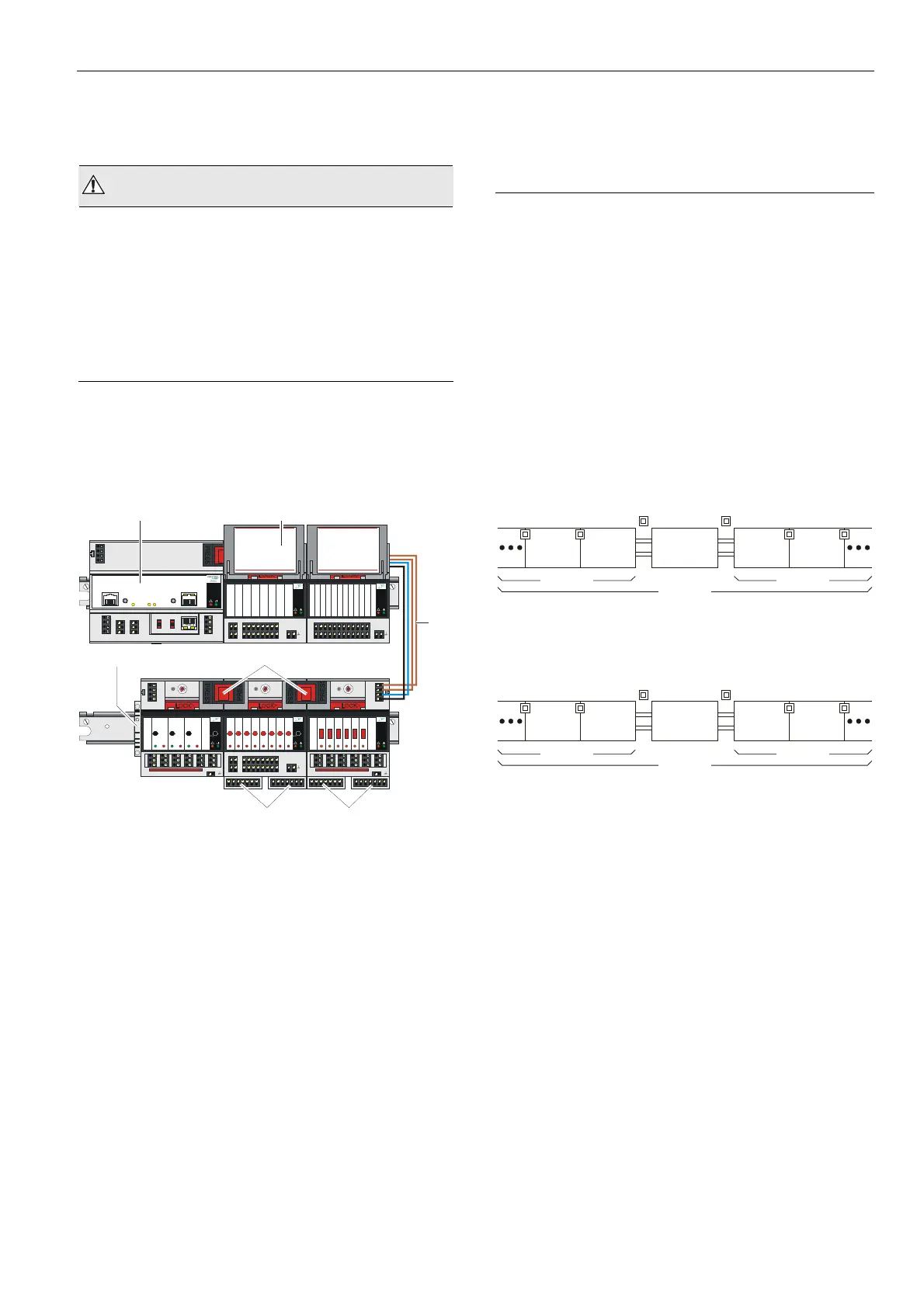
Fig. 13 CLLIONLC01
Controller Module and I/O modules
mounted on multiple DIN rails
Legend
1 CLLIONLC01 Controller Module
2 Swivel label holder
3 Cable connection
4 Stopper (from 3
rd
-party supplier)
5 Bridge connectors
6 Auxiliary terminal package
Mounting/Dismounting Controller/Sockets
Mounting Sockets
Notes
• When using both Panel Bus and L
ON
W
ORKS
Bus I/O
modules in an Excel 800 LION System, group both
Panel Bus modules (light gray) and L
ON
W
ORKS
Bus I/O
modules (dark gray), e.g., on different rails.
• Up to 10 Panel Bus I/O modules can be mounted to one
side of the controller. In total, up to 16 Panel Bus
I/O modules can be mounted to one controller.
• The CLLIONLC01 Controller Module is mounted on the
DIN rail in the same way as a terminal socket.
CLLIONLC01
BUS
I/O
PANEL
BUS
I/O
BUS
I/O
PANEL
BUS
I/O
max. 10
max. 16
Fig. 14 Max. number of Panel Bus I/O modules
CLLIONLC01
LonWorks
BUS I/O
BUS
I/O
max. 10
max. 20
BUS I/O
LonWorks
BUS I/O
LonWorks
BUS I/O
Fig. 15 Max. number of L
ON
W
ORKS
Bus I/O modules with
power supply via CLLIONLC01

 Loading...