ES-50X Series Manual — P/N LS10129-000FL-E:E 5/23/2022 15
Controls and Indicators Product Description
Primary ANN-BUS - TB9
Class A or Class B wiring
ANN-BUS annunciator connector, Terminal 1 (+/A) and Terminal 2 (-/B)
Class A wiring uses Terminal 3 (+/A Return) and Terminal 4 (-/B Return)
Annunciators require non-resettable power
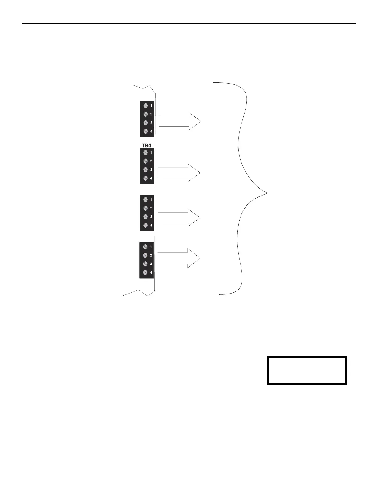
The following figure illustrates the maximum current that is possible for each major panel output circuit and the total current available from
the FACP.
1.3 Controls and Indicators
LCD Display
The FACP uses an 80-character
(4 lines X 20 characters) high viewing angle LCD display. The display includes a long life LED
backlight that remains illuminated. If AC power is lost and the system is not in alarm, the LED
backlight will turn off to conserve batteries.
Key Panel
Mounted on the main circuit board, the key panel includes a window for the LCD display and
LED indicators as listed below. The key panel, which is visible with the cabinet door closed, has 30 keys, including a 16 key alpha-numeric
pad similar to a telephone keypad.
Figure 1.1 Current Availability
powerdistes50.wmf
Refer to the battery calculations section for additional information.
Special Application
Nonresettable or
Resettable Power
NAC #1
NAC #2
Remote Synchronization
Output
1.0 amp max
per circuit
2.5 amps max
per circuit
Alarm
3.0 amps max
per panel
0.35 amp max
per circuit
2.5 amps max
per circuit
Standby
2.0 amps max
per panel
SYSTEM NORMAL
10:00A 010118
 Loading...


