Appendix G: Peripherals Galaxy Flex Installer Manual
250
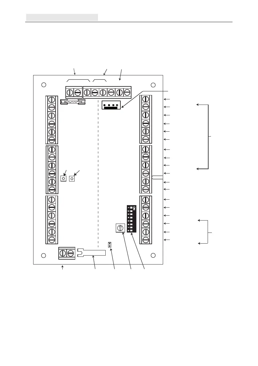
Wiring the reader to the DCM
The wires from the Reader are connected to the Wiegand Reader Inputs (see Figure 17).
Refer to separate Reader instructions for method of wiring the Reader to the DCM.
Shield
U EXT
0V
D0/
CLK
D1/
DATA
LED
Red
LED
Yel
LED
Grn
BUZ
BC
0V
EC
DC
0V
FC
NC
C
NO
Shield
U EXT
0V
D0/
CLK
D1/
DATA
LED
Red
LED
Yel
LED
Grn
BUZ
BC
0V
EC
DC
0V
FC
NC
C
NO
RS485
BUS1/2
Shield
U in
0V
Data
0V
0V
A
B
12 V
input
Bus 1/2 not
supported
RS485
connector
Common pin for connecting
cable shield or drain wire
12 volt output
0 volt connect
DO (Data Out)
DI (Data In)
LED 1
LED 2
LED 3
Buzzer output for reader
1
2 3
4 5
6
7 8
ON
Not Used
0 volt connect
RTE contact
Door contact input
0 volt connect
Function contact
(menu button)
Normally closed relay
Common pin relay
Normally open relay
TC 0V
Lid tamper
switch
Tamper
connect
Rotary
address
Switch
DIP Switches
Engineer Header
Wiegand
Reader
Inputs
Relay
outputs
form C
Reader 1 Reader 2
Door 1
Door 2
Jumper for
lid tamper
LED 2
(power)
LED 1
(comms)
Figure 17 Door control module PCB
Note: If
only one door is being connected, then always use the connections for Door 1 (left
side) and terminate the inputs with a 1 k resistor.

 Loading...


