Galaxy Flex Installer Manual Appendix G: Peripherals
251
Connecting a Wiegand device
A standard Wiegand card reader or keypad can be connected to the DCM. The keypad can
operate in 4-bit and 8-bit burst mode.
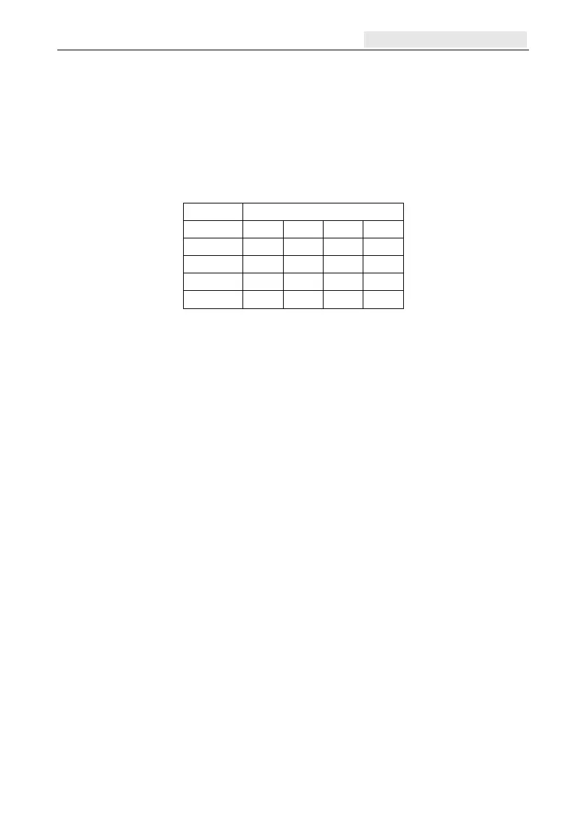
Addressing with DIP switches
Using the DIP switches set the DCM address to a unique value before it is connected to a
power supply. The following table shows each DIP switch with related address number. Set
switches 4 to 8 in the off position.
Switch
Address
1 2 3 4 to 8
0 OFF OFF OFF OFF
1 ON OFF OFF OFF
2 OFF ON OFF OFF
3 ON ON OFF OFF
Connecting the DCM to the system
Wire the DCM to the RS485 line. The DCM requires 12 V d.c., which can be supplied from
the control panel power supply or from the Power RIO when mounted inside the Power RIO
box (see Figure 17).
Note: If the DCM is the last module on the line, connect a 680 Ω EOL resistor across the
A and B terminals.
Configuring the DCM
The DCM is configured into the system on power up of the control panel or when exiting
from engineer mode. The flash rate of the green comms LED (LED 1) on the DCM indicates
the status of the communication with the control panel. A short flash once per second
indicates good communications. LED 2 when lit indicates that there is power to the DCM.

 Loading...


