IntuVue RDR-4000 Weather Radar Pilot's Guide
060-4492-000 Principles of Weather Radar Use
Rev 7, February 2015 31
SECTION 4: EQUIPMENT DESCRIPTION
UNIT DESCRIPTIONS
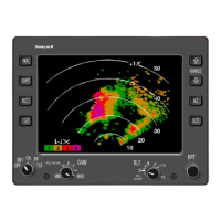
RP-1 RADAR PROCESSOR
The Radar Processor contains the electronics
necessary to process the radar data received from
the transmitter/receiver, control the modes of the
radar, and format the radar data for display. The
RP-1 is normally located in the Forward EE-Bay.
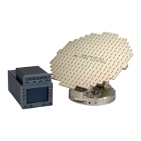
TR-1 TRANSMITTER/RECEIVER
The Transmitter/Receiver contains the electronics
necessary to transmit, receive, and process the
radar pulses used to detect turbulence, windshear,
weather, and terrain targets. It also contains the
system integrity monitoring and self test electronics.
The TR-1 is located in the radome in the base of the
antenna drive.
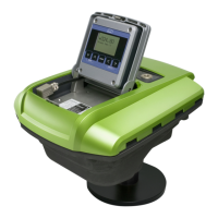
DA-1A/B WITH FP30-1 ANTENNA DRIVE
The component parts of the antenna drive are the
DA-1A (single) or DA-1B (dual) Antenna Drive and
the FP30-1 flat-plate array. The antenna drive,
located within the radome, forms the microwave
energy into a 3-degree beam. The antenna also
receives the return microwave energy, after
reflection by weather formations or other objects,
and routes these signals to the transmitter/receiver
for processing. The antenna drive scans a
160-degree sector in azimuth and ±15 degrees in
elevation (tilt).
 Loading...