Fire Alarm Control Panel IQ8Control C/M
FB 798951.GB0 / 01.09
23
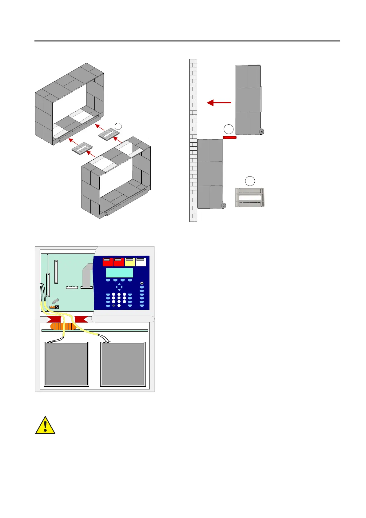
Connection between the central housing and the extension housing
1
1
1
2x connection pieces
with cable glands
1. Remove the appropriate 2 plastic plates from
panels and extension housing
2. Push the plastic connector bracket in each
originated gap. Observe the arrows on the bracket
for the right direction.
3. Push the upper housing via the guide way of the
brackets towards the wall.
4. Align both connection brackets to ensure that the
cables between the housings may be lead through
the openings of the brackets.
5. Each housing must be fixed with suited screws
(4x) and dowels without twisting stress.
Fig. 17: Knockouts for battery cable
Damage to the system!
Take care to ensure that no cables are pinched or damaged.
Each housing part must be separately fixed to the mounting place. The plastic connection brackets are
not suited to carry the weight of the lower housing alone.

 Loading...


