Scanner and Cable Terminations
Scanner Pinout Connections
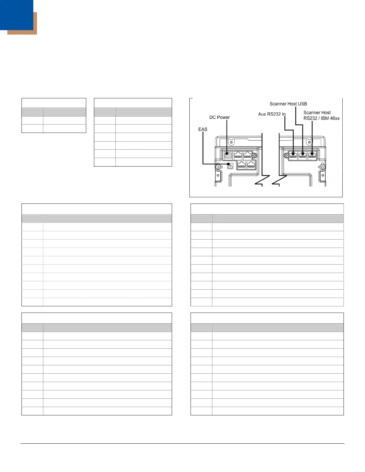
The MS2421/MS2422/MS2431 scanner terminates to 10-pin modular jacks located on the bottom of the unit.
The serial number label indicates the model number and interface of the scanner.
EAS
DC Power
Pin Function
Pin Function
1 EAS In
1
No Connect
2 EAS Out
2 Earth Ground
3
No Connect
4 5.2VDC
5 Ground
6 12VDC
Figure 39. Connector Layout
Scanner to Host, RS485
Scanner to Host, RS232
Pin Function
Pin Function
1 Signal Ground
1 Ground
2
Reserved for RS232 Interface
2 RS232 Transmit
3
Reserved for RS232 Interface
3 RS232 Receive
4
Reserved for RS232 Interface
4 RS232 RTS Output
5
Reserved for RS232 Interface
5 RS232 CTS Input
6
Reserved for RS232 Interface and EAS
6 RS232 DTR Input (EAS GPIO IN)
7
No Connect
7
No Connect
8
Reserved for RS232 Interface and EAS
8 DSR (EAS GPIO OUT)
9 IBM B-
9
Reserved for RS485 Interface
10 IBM A+
10
Reserved for RS485 Interface
Scanner to Host, USB
Auxiliary RS232 In
Pin Function
Pin Function
1 Signal Ground
1 Ground
2 RS232 Transmit
2 RS232 Receive Input
3 RS232 Receive
3 RS232 Transmit Output
4 Shield
4 RS232 RTS In
5
No Connect
5 RS232 CTS Out
6 RS232 CTS Input (EAS GPIO IN)
6 EAS GPIO IN
7 PC+5VDC
7 Ground
8 RS232 RTS Output (EAS GPIO OUT)
8 EAS GPIO OUT
9 Data -
9 +5V Out
10 Data +
10
No Connect
Specifications are subject to change without notice.
51