24 www.honeywell.com
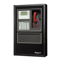
NetAXS™ NX4S1 Installation
Installation
Note: If a MIRO 32/0 is not required in a system, start addressing the 2/16 modules at
DIP switch 3. If a MIRO 32/0 is configured with an address other than 1 or 2, the
NetAXS™ panel will not communicate with it. Likewise, if a MIRO 2/16 is
configured with an address other than 3 through 6, the NetAXS™ panel will not
communicate with it.
The NetAXS™ board is not intended to provide either module power or module
output load power for downstream I/O. A separate 24VDC supply should be used to
provide power to all downstream modules and output loads. For some installations,
the noise immunity improves if the NetAXS™ common is connected to the 24 VDC
Return wiring for the downstream modules. This connection is not needed for most
installations.
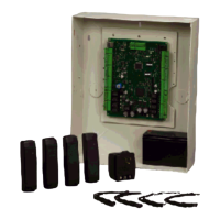
Jumper settings JP1 - CLOSED (if the module is
the last module on the
downstream bus), OPEN (if the
module is not the last module on
the downstream bus)
JP2 - any setting
JP3 - any setting
JP4 - NORMAL
(Positions 1 and 2)
MIRO 2/16 DIP switches Address (switches 1-6) - 3
through 6
Baud rate (switches 7 and 8) - 7
= OFF, 8 = ON
OP Mode (switches 9 and 10) - 9
= OFF, 10 = OFF
Jumper settings JP1 - CLOSED, positions 2 and
3 (if the module is the last
module on the downstream bus);
OPEN, positions 1 and 2 (if the
module is not the last module on
the downstream bus)
JP2 - NORMAL, positions 1
and 2
Table 4 MIRO 32/0 DIP Switch and Jumper Settings (continued)
Module Setting Value
 Loading...