11
The Gateway Board’s Layout
2.3.3 Switches on the Gateway Board
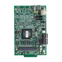
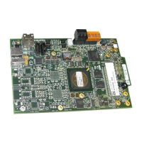
Below table describes about the switches on the gateway board. To locate the switches on the gateway
board, refer
Figure 2.1: “Printed Circuit Board: Layout” on page 7
.
Table 2.3: Gateway Board Switches
DL7
Cellular Connectivity
Indicates the gateway connectivity status with cellular devices.
FLASHING SLOW (flashes per 1 second). The cellular connectivity is enabled for the
Cloud connection.
OFF The cellular connectivity is disabled.
Switches Purpose
S6 For securely configuring the gateway’s network settings. Pressing the switch for
six seconds switches the gateway board to the configuration mode.
S7 For changing the direction of the 24V power of the NUP connector.
NUP IN: The gateway board receives power from the NUP connection.
NUP OUT: The gateway board supplies power to the NUP connection.
S8 For enabling mobile pairing. Pressing the switch for ten seconds enables mobile
pairing.
S6 and S8 For reverting to factory default settings. Pressing both of them together for ten
seconds will start the factory resetting process. The factory resetting process
takes 10 minutes to complete.
Tamper 1 For alerting whenever the door is opened. It is located at the front-side of the
gateway, next to the LED indicators.
Tamper 2 For alerting whenever the gateway board is removed from the enclosure. It is
located at the backside of the gateway.
 Loading...
