Setpoint Rate/Ramp/Soak Program Operation
5/00 UDC3300 Expanded Model: DC330E User Manual 67
Selecting Tuning Parameters for Each Group
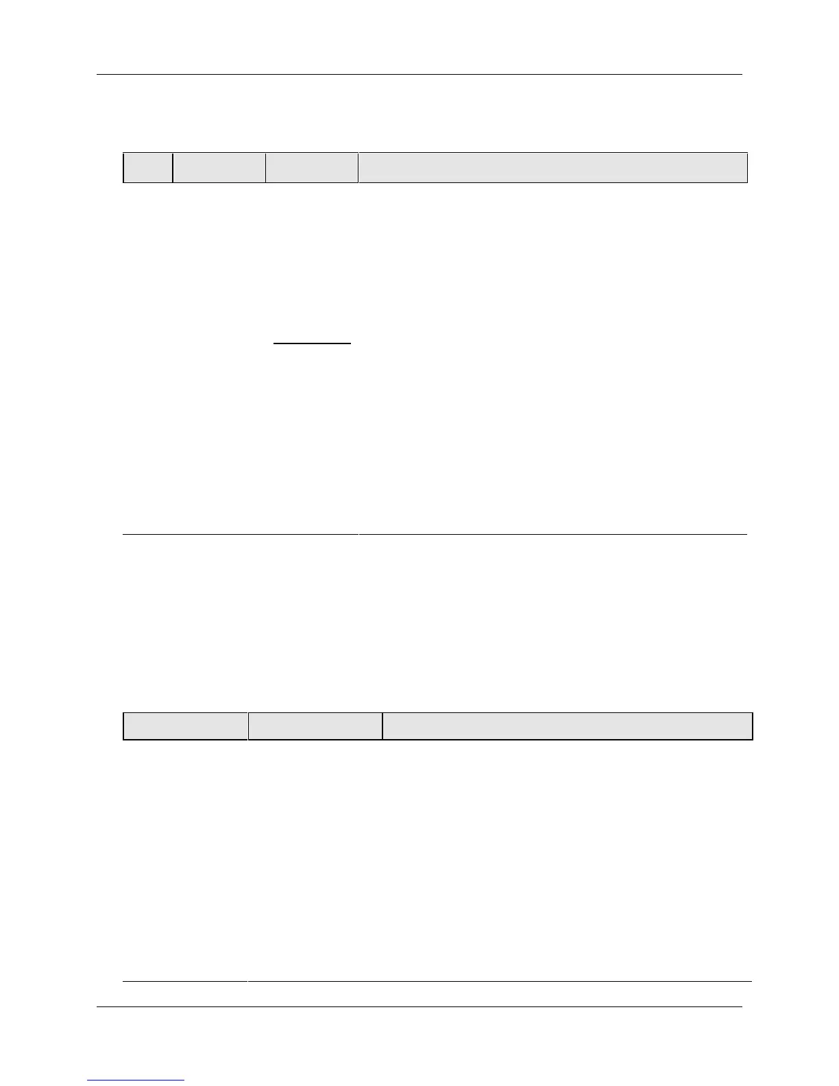
Table 4-16 Procedure for Selecting Tuning Parameters
Step Operation Press Action
1
Select
Tuning Set
Up Group
SET UP
until you see: TUNING FOR Loop 1 or TUNING2 for
Loop 2.
PID sets 1 and 2 (TUNING) are for Loop 1 and single
loop applications.
PID sets 3 and 4 (TUNING 2) are for Loop 2 in two-loop
and cascade control applications.
2
Select
Tuning
constants
FUNCTION
LOOP 1/2
to successively display the constants for the Primary
Loop OR Loop 2.
Refer to Section 3 - Configuration for detailed
information.
You can Autotune both sets on either loop. Refer to
Section 4.15.
Use the FUNCTION key to switch between loops for
display and monitoring.
▲ or ▼
to change the values.
4.9 Monitoring Two Loops of Control
Loop Display
Display of Loop 1 or Loop 2 (if configured) is selected by toggling the
FUNCTION / LOOP 1/2 key.
The indicator which identifies which loop is being monitored is displayed in the left-
most character in the Upper Display
Table 4-17 Digital Display Indication—Two Loops
Loop Indicator Loop Indication Definition
None
(If Two Loops
are configured)
I
(If cascade is
configured)
Loop 1 is being
displayed.
• Upper display shows the Process Variable (PV) for
Loop 1
• Lower display shows the Loop 1 parameters and
the PV and Output for Loop 2
• Controller setpoint annunciators show the setpoint
currently being used for Loop 1
L”
Loop 2 is being
displayed
• Upper display shows the Process Variable (PV) for
Loop 2
• Lower display shows the Loop 2 parameters and
the PV and Output for Loop 1
• Controller setpoint annunciators show the setpoint
currently being used for Loop 2
 Loading...


