Calibration Handbook
115Series 3000 XPIS
Series 3000 XPIS Calibration Procedure
The following equipment is required:
s Appropriate span gas cylinder
s Flow regulator set to 300-375mL/min
s Tubing
s Magnet
s Calibration gas flow housing
NOTE
gas. If no residual gas is present then background air can be used to perform zero.
Zero and Span Calibration
CAUTION
Before initial calibration allow the detector to stabilize for 30 minutes after applying power. When in zeroing
and span calibration mode the current output from the detector is inhibited (default 3mA) to avoid false alarms.
It is recommended for most sticky gases the tubing should be PTFE with short pieces of rubber tube to make
allows for more accurate measurement.
NOTE
is to be used. Re-calibration is recommended if the temperature of local environment has varied by more
It is essential that the sensor is tested frequently to be sure the system is operating properly. Typically gas
environmental conditions and in the presence of other gases. It is the responsibility of the user to determine
an appropriate calibration frequency for the application.
1. If using compressed air, push the calibration gas flow housing onto the bottom of the sensor and apply
the gas.
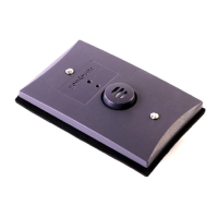
2. To access the calibration mode, hold the end of the magnet over the switch located at the top centre of
the detector display for at least 5 seconds and then remove.
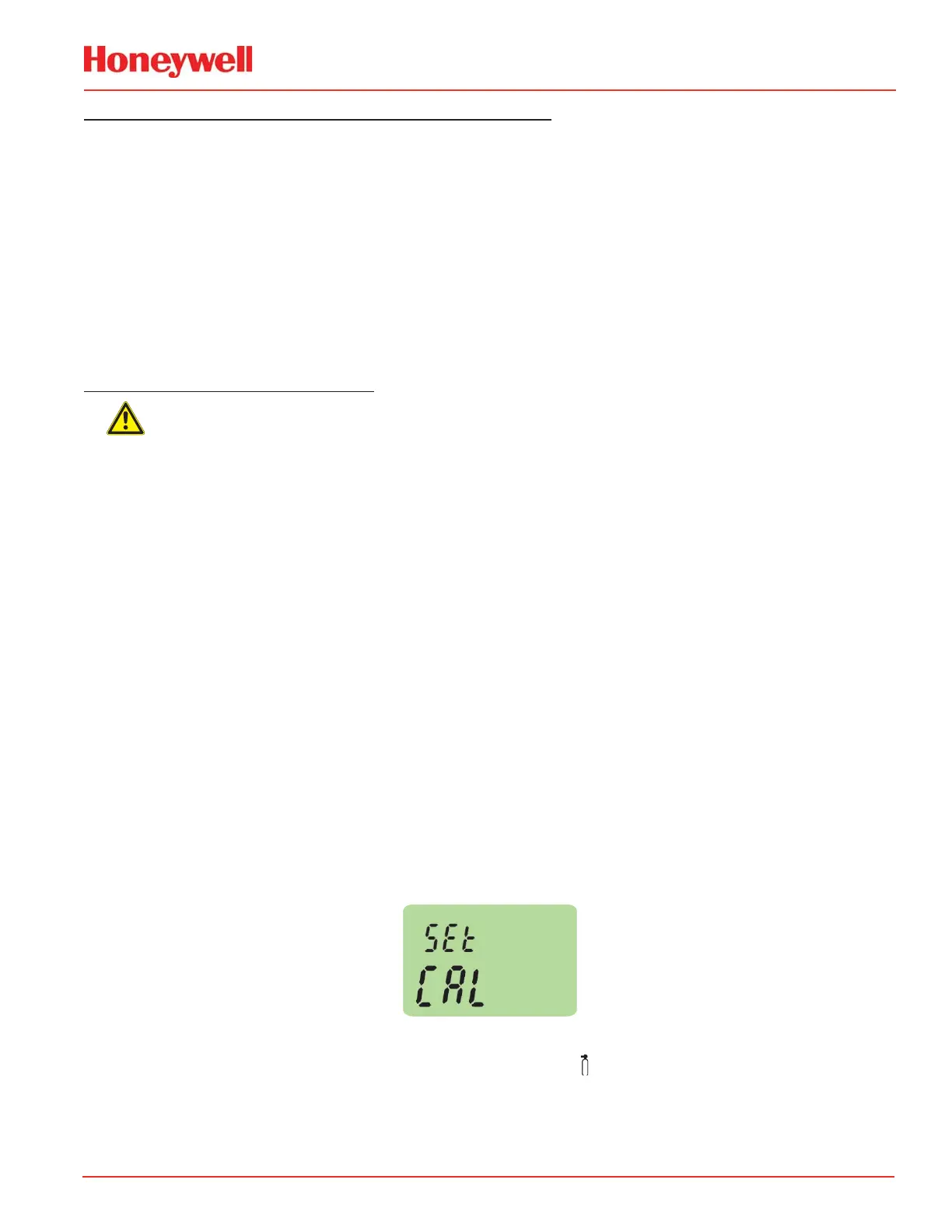
3. The display will indicate the first menu mode menu ‘SEt CAL’.
4. Place magnet over the ‘✓’ switch and remove to enter the Calibration menu.
5. The display will show the current gas reading, ‘ZEro’ and the ‘
’ icon flashes.
 Loading...