Installation Instruction VARIODYN
®
D1 System
60 FB 798663.GB0 / 05.19
7.2.1 DIP-Switch 2XD-Series
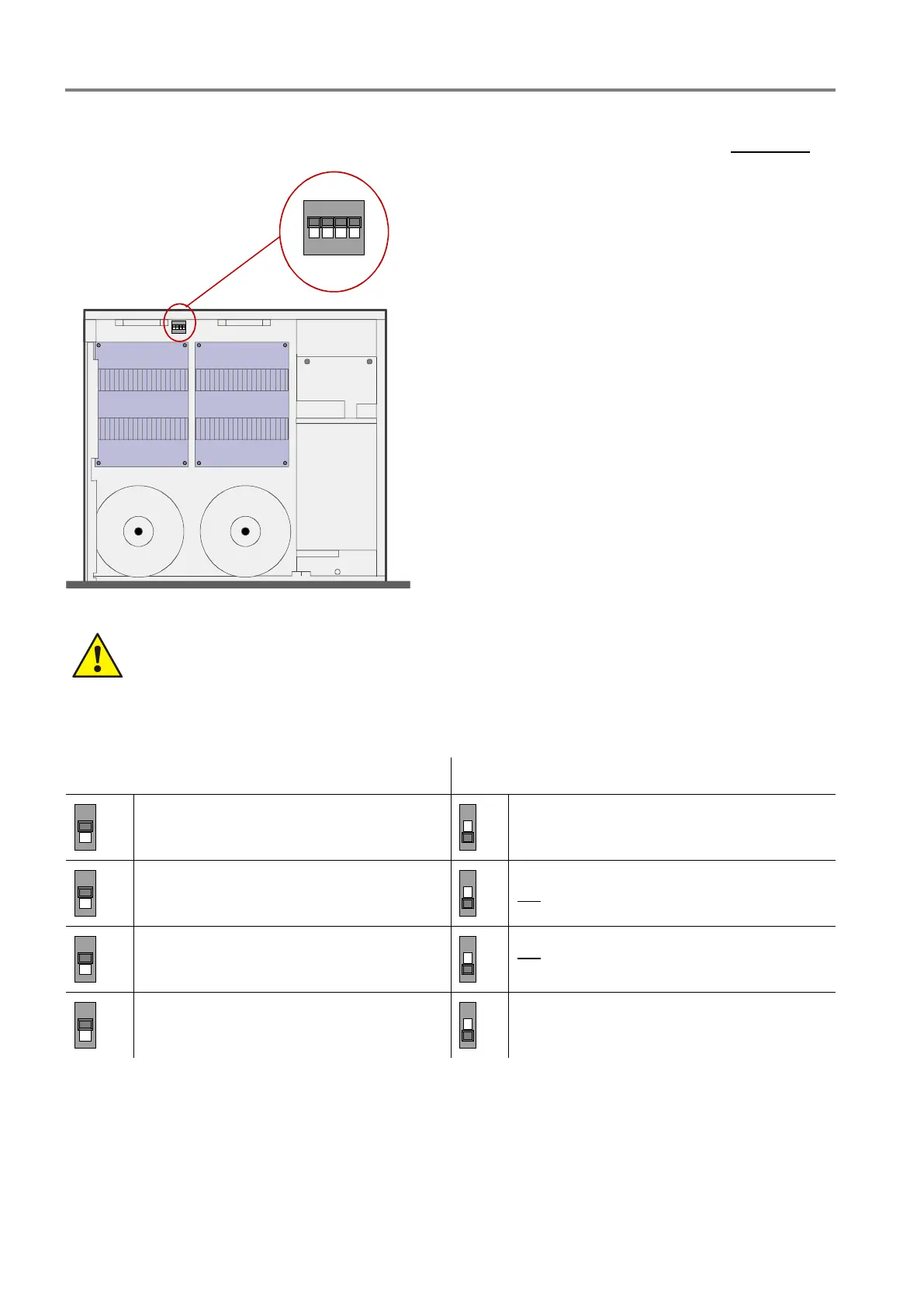
The housing of the amplifier must be opened to configure the DIP switch. Disconnect the system beforehand!
Fig. 52: Position of the DIP-Switch SW1
Danger – Electric shock!
Assembly and installation work may only be performed when the system is de-energised (voltage free).
ESD / EMC preventive measures
Before handling electronic modules, always take suitable precautions to prevent static electricity.
Set required DIP switch SW1 position as given in the table below:
SW1 = OFF (factory setting) SW1 = ON
LED of channel 1 and 2 lit to indicate an
audio signal that exceeds -20 dB
LED of channel 1 and 2 lit to indicate an
audio signal that exceeds -6 dB
Automatic reset of a system fault after
2 minutes
NO automatic reset of a system fault
Monitored 24 V DC Backup supply voltage
NO monitoring of the 24 V DC Backup
supply voltage
Not used
Not used
 Loading...