Do you have a question about the Honeywell VARIODYN D1 and is the answer not in the manual?
Details the intended use, standards compliance, and system designations for voice alarm systems.
Defines the operator's duties for system design and operation, including local standards.
Lists essential documents for installation and configuration of VARIODYN® systems.
Outlines relevant standards and regulations applicable to voice alarm systems.
Details the specifications and declarations of performance for EN 54 standards.
Provides a system overview for building-specific configurations and alarm purposes.
Explains how the system can achieve a redundant structure with specific devices.
Lists components and their maximum numbers for system configuration protocols.
Details required cable types and specifications for system installation.
Provides an overview of system cables required for connecting devices in the installation cabinet.
Details required cable cross-sections for loudspeaker loops based on power and length.
Specifies maximum distances for Loop Isolator Modules based on cable cross-section.
Guidelines for using factory-provided cable entries and securing lines.
Details wiring methods for loudspeaker spurs, including EOL modules for monitoring.
Explains loudspeaker connection using loop technology with standardized cable monitoring.
Specifies conditions for floor type cabinet installation, including access and load capacity.
Guidance on visibility of visual displays when installing devices.
Information on installing heavy devices and power amplifiers, including mounting brackets.
Requirements for cabinet ventilation to prevent heat accumulation.
Details an optional kit for switching off the emergency power supply/batteries.
Presents individual system components suitable for rack mounting with their part numbers.
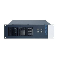
Describes VARIODYN® cabinet systems, their design, and HU specifications for rack mounting.
Describes the DOM as the central control element for connecting components and managing loudspeaker circuits.
Details the integrated lithium battery for customer data protection and its replacement procedure.
Provides detailed technical specifications for the Digital-Output-Module (DOM), including audio and input parameters.
Explains flexible applications of DOM with 2XD and 4XD amplifiers for optimal channel configuration.
Describes the VCM for displaying messages and operating via integrated buttons, requiring one VCM per VAS cabinet.
Provides technical specifications for the View-Control-Module (VCM), including power, environment, and dimensions.
Details the MSU for safeguarding power supply to VARIODYN® D1 components, connecting up to three devices.
Explains the use of a neutral conductor monitoring module for power interruption in case of faults.
Provides detailed specifications for the Main Switch Unit (MSU), including thermal fuse protection and auxiliary contacts.
Describes the UIM as an interface for audio inputs/outputs and 48 control contacts, connecting to DOM via DAL bus.
Provides technical specifications for the Universal Interface Module (UIM), covering audio and control contact interfaces.
Describes the SCU as a digital audio memory for voice information, music, and alarm storage.
Explains how to connect the SCU to a VARIODYN® D1 network and power supply.
Details the integrated lithium battery for SCU data protection and its replacement procedure.
Provides technical specifications for the System Communication Unit (SCU), including power, environment, and capacity.
Guides amplifier selection based on output power, and emphasizes proper ventilation for cabinet installations.
Describes 2XH series power amplifiers providing two independent amplifier channels.
Explains the configuration of DIP switches for 2XH series amplifiers, including fault indications.
Describes 2XD series power amplifiers offering two independent amplifier channels (double final amplifiers).
Details the DIP switch settings for 2XD series amplifiers to configure functions like audio signal indication and fault resets.
Illustrates the connection of 2XH and 2XD series power amplifiers to the MSU, DOM, and other components.
Provides detailed specifications for 2XH and 2XD series power amplifiers, including voltage, current, and output power.
Introduces 4XD series power amplifiers with four independent amplifier channels.
Covers DIP switch settings for various 4XD amplifier models for configuration and monitoring.
Introduces 4XV series power amplifiers with four independent amplifier channels.
Describes 4XV300/4XV500 amplifiers, detailing their features and connections.
Illustrates connecting DOM and Power Amplifiers for 4XD and 4XV series using specific cables.
Provides specifications for 4XD and 4XV series amplifiers, including voltage, current, output power, and dimensions.
Explains using backup amplifiers for redundancy across different series (2XH/2XD, 4XD/4XV).
Explains using one backup amplifier for multiple DOMs in 2XH/2XD series for redundancy.
Details using one backup channel for 4XD125B/4XD250B amplifiers for 3:1 backup operation.
Explains using one backup amplifier for multiple DOMs in 4XD/4XV series for 6 DOM backup.
Describes the back-up power supply (Part No. 581721) for independent system power, including fault indicators.
Describes PSU 24V-2/24V-2 net for independent system power, detailing fault and output indicators.
Details PSU 24V-4/24V-4 net for independent system power, including fault and output indicators.
Explains connecting emergency power supply units to components like amplifiers and control units, including battery connection.
Details the PE and FE connections for the housing to the PE rail and equipotential bonding.
Lists various devices and accessories connectable to the VARIODYN® D1 System.
Lists key features of the Designer D1 software for planning and configuring VARIODYN® D1 systems.
Provides information on the Open Source Software used in the VARIODYN® D1 product.
| Brand | Honeywell |
|---|---|
| Model | VARIODYN D1 |
| Category | Network Hardware |
| Language | English |