Installation Instruction VARIODYN
®
D1 System
FB 798663.GB0 / 05.19 41
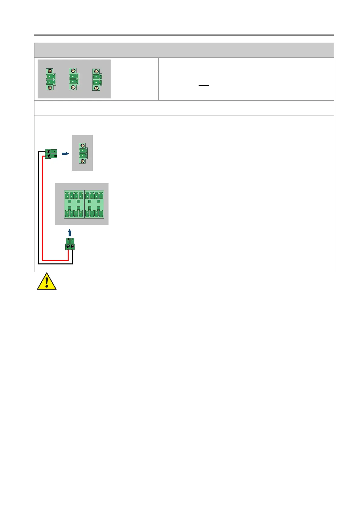
Connection of the DOM
LIVE SIGNAL
DOM 2
DOM 1 DOM 3
Monitoring of the life sign signals takes place via the control
contacts of DOM 1. Use cable type I-Y (St) Y 2 x 2 x 0.8 mm and
the enclosed two-
pin plug to make the connection. The
connection to one DOM is sufficient for monitoring of the life sign
signals.
Max. cable cross-section: 1.5 mm²
Connection example
DOM
DOM 1
CONTACTS
1 2
5 6
3 4
7 8
VCM
DOM 1
• Do not connect terminals DOM 2 and DOM 3.
• For the connection diagram of the DOM inputs/outputs, see chapter 6.1.
6.2.1 Specification - VCM
Back-up power supply : 24 V DC
Power consumption : 10 mA @ 24 V DC
Air Humidity : 40 % … 90 % rel. hum. (non-condensing)
Ambient temperature : -5 °C … +55 °C
Storage temperature : -10 °C … +60 °C
Housing : metal
Colour : grey, similar to RAL 716
Weight : approx. 0,9 kg
Dimensions (W x H x D) : 483 x 44 x 33 mm (1 HU)
Specification : EN 54-16
 Loading...