Installation Instruction VARIODYN
®
D1 System
40 FB 798663.GB0 / 05.19
View-Control-Module (VCM) UIM and DOM connection
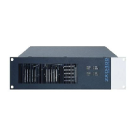
Connection of the VCM
The collective messages are passed on to the VCM
via the control contacts of the UIM and displayed on
the VCM. Use the prefabricated cable for the
connection.
Connection example
UIM
CONNECTION UIM
DIGITAL I/O
DIGITAL I/O
GND 1
2
3 4 5 6 7 8 9 10
11
12
GND
GND
GND13 14
15 16
17
18
19
20
21
22
23
24
25 26 27 28 29 30 31
32
34
35
36
37
38
39
40
41
42
43
44 45
46
47
48
33
VCM
UIM
For the connection diagram of the UIM inputs/outputs, see chapter 6.4.
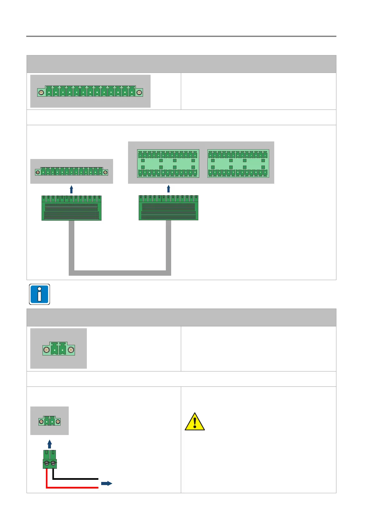
24 V DC power supply
The supply of 24 V DC to the VCM takes place via
the 24 V DC emergency power supply. Use cable
type I-Y (St) Y 2 x 2 x 0.8 mm and the enclosed two-
pin plug to make the connection.
Max. cable cross-section: 1.5 mm²
Connection example
24 V DC
to 24 V DC
back-up power supply
VCM
+ 24 V -
Danger – Electric shock!
Assembly and installation work may only be
performed when the system is de-energised
(voltage free).
ESD / EMC preventive measures
Before handling electronic modules, always
take suitable precautions to prevent static
electricity.
 Loading...